Expandable tubular fabric

a tubular fabric and expandable technology, applied in the direction of insulated conductors, cables, pedestrian/occupant safety arrangements, etc., can solve the problems of relatively slow referred to forming methods and relatively high cos

Inactive Publication Date: 2006-12-12
EVELYN FLORENCE
View PDF14 Cites 54 Cited by
  • Summary
  • Abstract
  • Description
  • Claims
  • Application Information

AI Technical Summary

Benefits of technology

The present process involves creating arrays of wires by adding them onto a cylindrical surface called a mandle that moves back-and forth over time. This allows for precise placement of wire bundles on different parts within the fabric being manufactured. By doing this, it simplifies the production processes needed and improves product quality control.

Problems solved by technology

The technical problem addressed in this patent is to provide a faster and less costly method of forming an expandable tubular fabric that is both longitudinally stable and secure in its position. Additionally, the fabric should have an open structure to allow for the extended use of internally carried elements.

Method used


Image

  • Expandable tubular fabric
  • Expandable tubular fabric
  • Expandable tubular fabric

Examples


Embodiment Construction

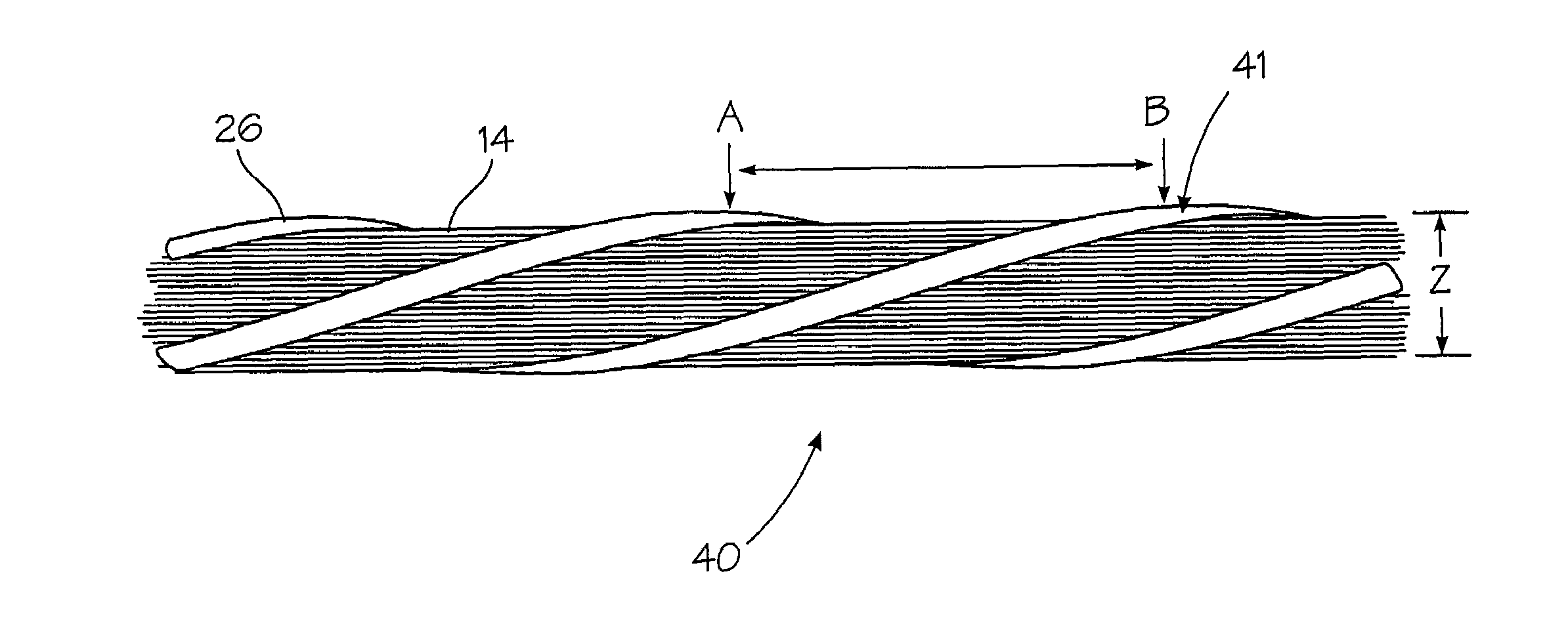
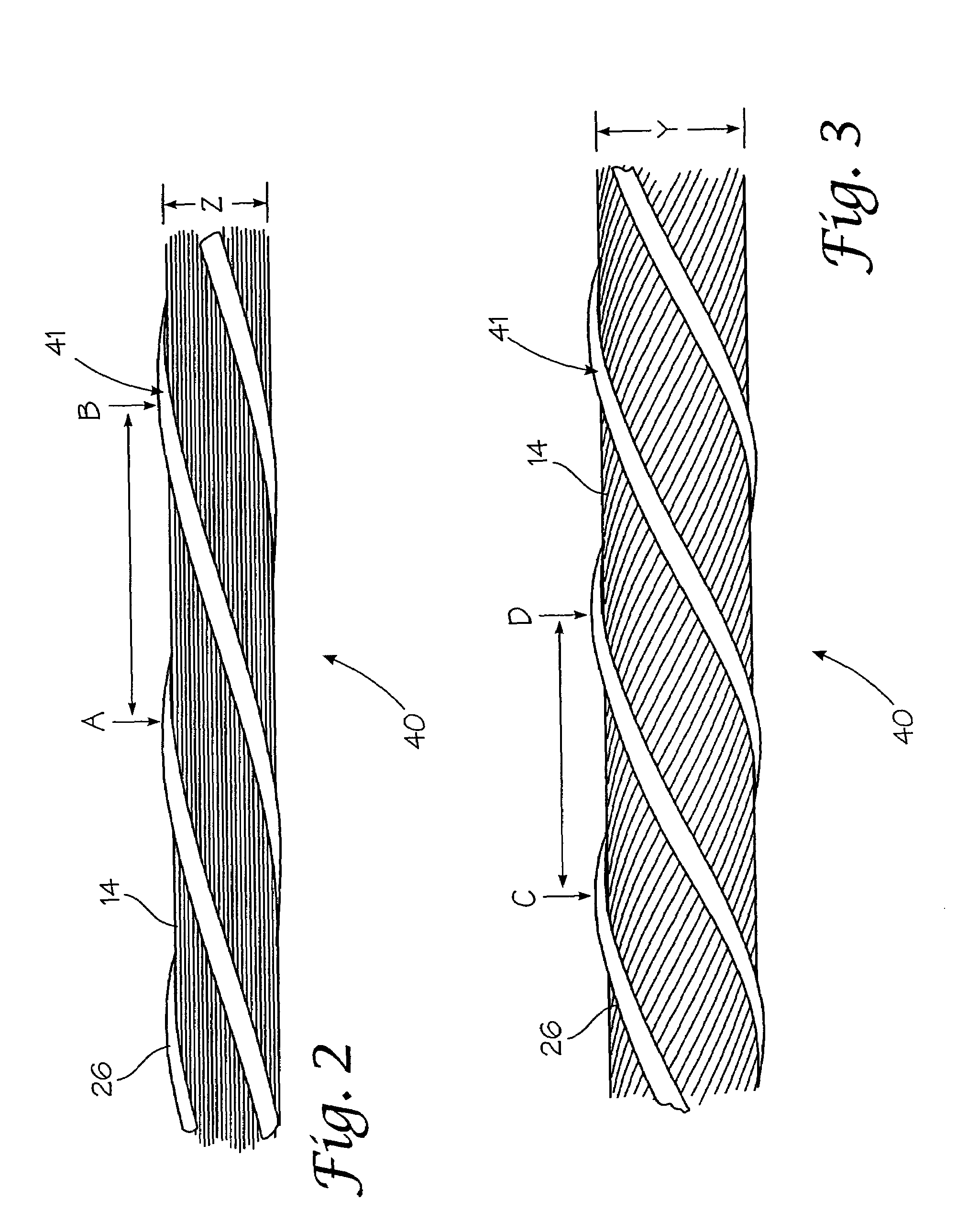
[0028]The term expandable tubular fabric is intended to describe an expandable tubular sheath which may be used to encase wires, cables, or bundled elements to provide protection or structure.

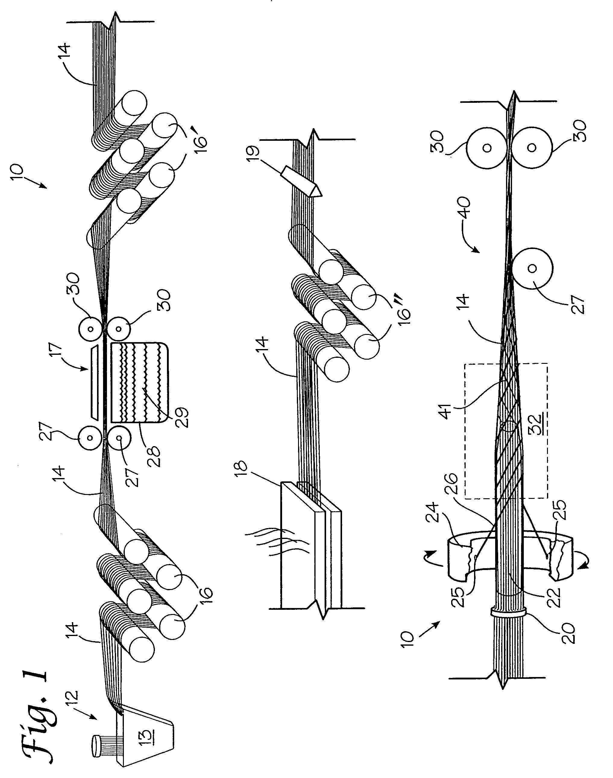
[0029]Turning now to FIG. 1, an arrangement 10 is shown for forming the expandable tubular fabric 40 of the invention. Yarns 14 are shown being drawn from supply or extruder 12 and passed through a quench tank 13. The yarns 14 then are directed around a plurality of draw rolls 16, through one or more stretch baths 17, and across additional draw rolls 16′. Successive roll stands rotate at higher speeds thereby drawing the yarns 14. The drawn yarns 14 are passed through one or more heat set ovens 18 to fix the desired elongation characteristics of the array of yarns 14 and then through additional draw rolls 16″.

[0030]It is noted that yarns 14 may alternatively comprise pre-formed yarns delivered from spools and pre-stretched and set to already have the desired elongation characteristics.

[0031]Arr...


PUM

PropertyMeasurementUnit
Lengthaaaaaaaaaa
Sizeaaaaaaaaaa
Elongationaaaaaaaaaa

Abstract

An expandable tubular fabric formed by heat setting a plurality of thermoplastic yarns producing drawn thermoplastic yarns, arranging these yarns in an array and in juxtaposed positions and moving them in a first direction. Extruding at least one filament along a circular or other shaped path about the moving array of drawn yarns and causing the extruded filament(s) to bond with the array of yarns. Finally, setting the extruded filament in bonded position with the array of yarns holding them in relative fixed positions and forming the fabric stable.

Description


Claims


Application Information

Patent Timeline
Owner EVELYN FLORENCE
Why Eureka
Try Eureka