Cooking vessel with multiply ringed bottom surface

a cooking vessel and bottom surface technology, applied in baking vessels, heating types, stoves or ranges, etc., can solve the problems of hiding copper and avoiding purchasing such products, and achieve the effect of protecting from abrasion during cooking

Active Publication Date: 2006-12-19
MEYER INTPROP
View PDF9 Cites 16 Cited by
  • Summary
  • Abstract
  • Description
  • Claims
  • Application Information

AI Technical Summary

Benefits of technology

[0007]In the present invention, the first object is achieved by forming a cooking vessel having a copper sheet or plate partially laminated between one or more exterior layers, such as stainless steel or another hard or durable material, with regions of the copper exposed where the hard or durable material is absent. Thus, the stainless steel extends from the bottom of the pan as a profile to protect the visible, but indented, copper layer from scratches and abrasion by the heaters or burner elements.
[0008]A second aspect of the invention is characterized in that the hard durable material in the exterior laminate layer is partially removed to expose one or more rings of copper that are concentric with the center of the pans, being recessed below the hard durable exterior layer and thus protected from abrasion during cooking.

Problems solved by technology

However, these constructions, while protecting the copper layer from abrasion that will degrade the appearance, also hide the copper.
This can be disadvantageous to manufactures as well, as the presence of copper in the construction will not be readily apparent to consumers, who might confuse such products with inferior merchandise.
Thus, consumers looking for copper based cookware, may readily forego purchasing such products although they might have nearly equivalent heat transfer properties compared to pure copper cookware products.

Method used


Image

  • Cooking vessel with multiply ringed bottom surface
  • Cooking vessel with multiply ringed bottom surface
  • Cooking vessel with multiply ringed bottom surface

Examples


first embodiment

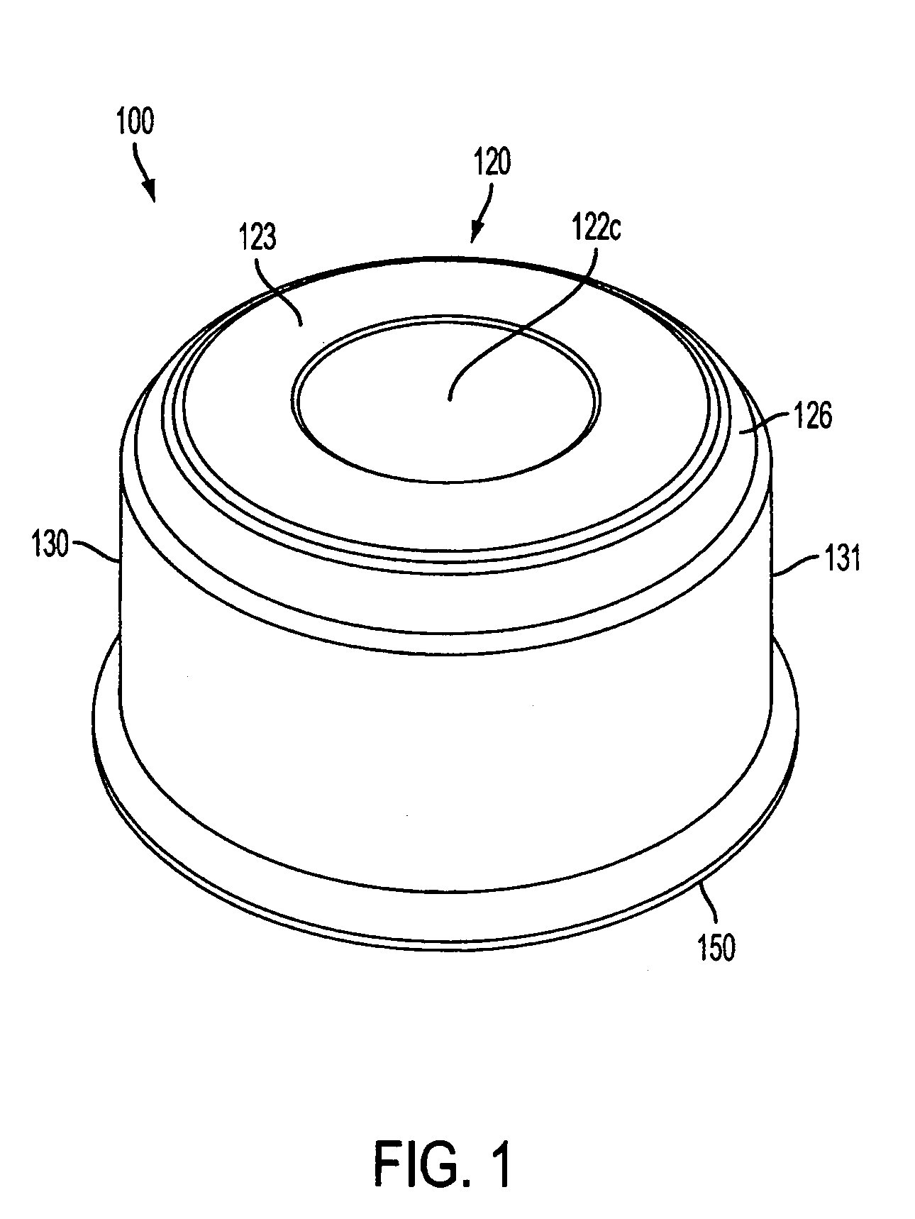
[0020]In accordance with the present invention, FIG. 1 depicts an inverted cooking vessel 100 of a first embodiment, in which external bottom surface 120 is upright and surrounded by upright wall 130 that extends therefrom, having outer surface 131. Upright wall 130 extends to outer rim to define the fluid retaining cavity 140. Accordingly, for the purposes of this illustration cooking vessel 100 may be considered to be resting on rim 150.

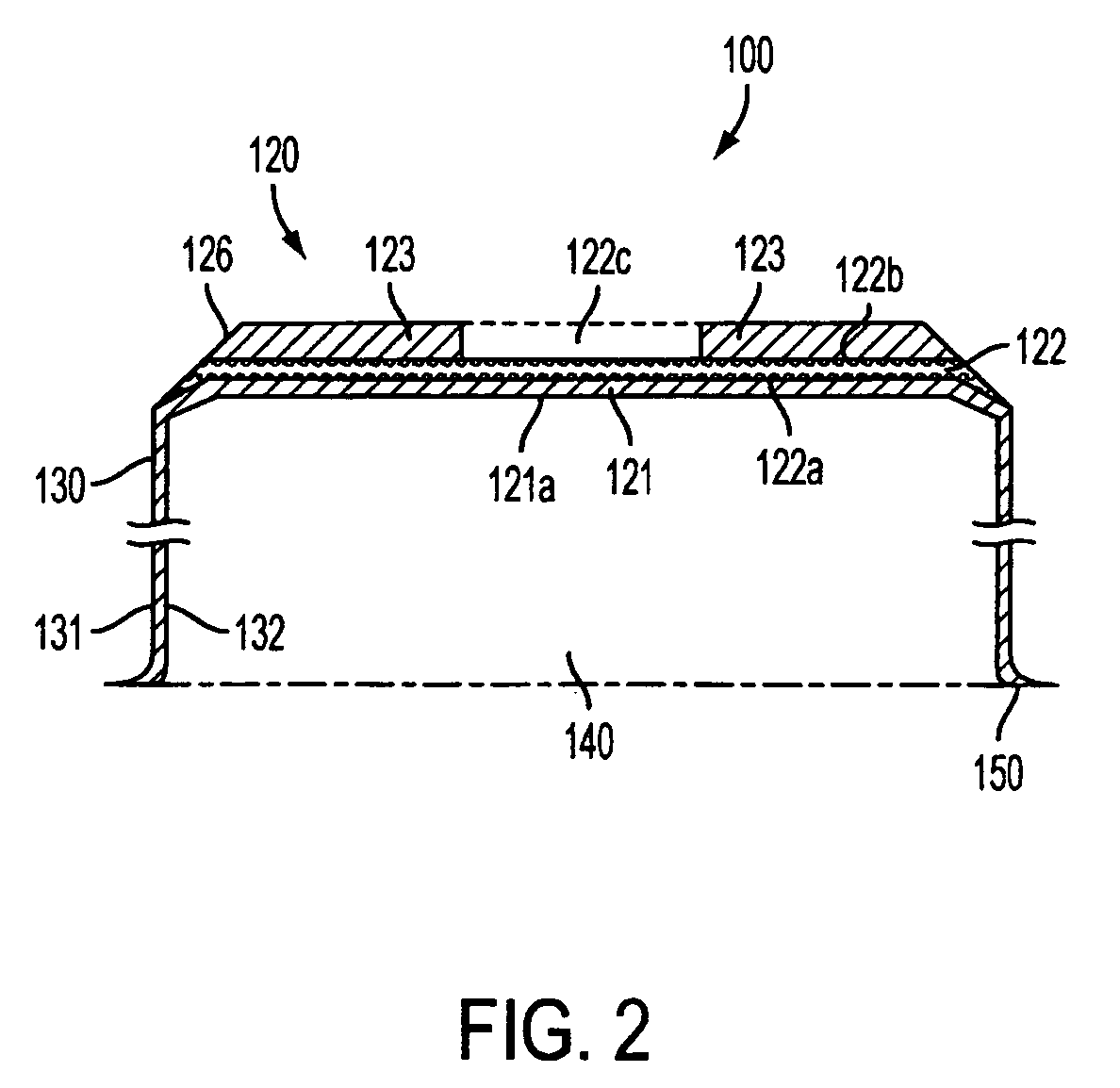
[0021]FIG. 2 is a cross-sectional illustration showing the laminate construction of cooking vessel 100 in FIG. 1 The bottom 120 of cooking vessel 100 comprises at least three layers of materials, with the upper or outer layer 123, (that is at the bottom of the pan when the FIG. is inverted for normal use) being discontinuous, as it extends above the middle layer 122. Accordingly, when cooking vessel 100 is resting on a burner or stove top in the normal non-inverted position, only the outer layer 123 makes contact with the supporting surface. While ...

second embodiment

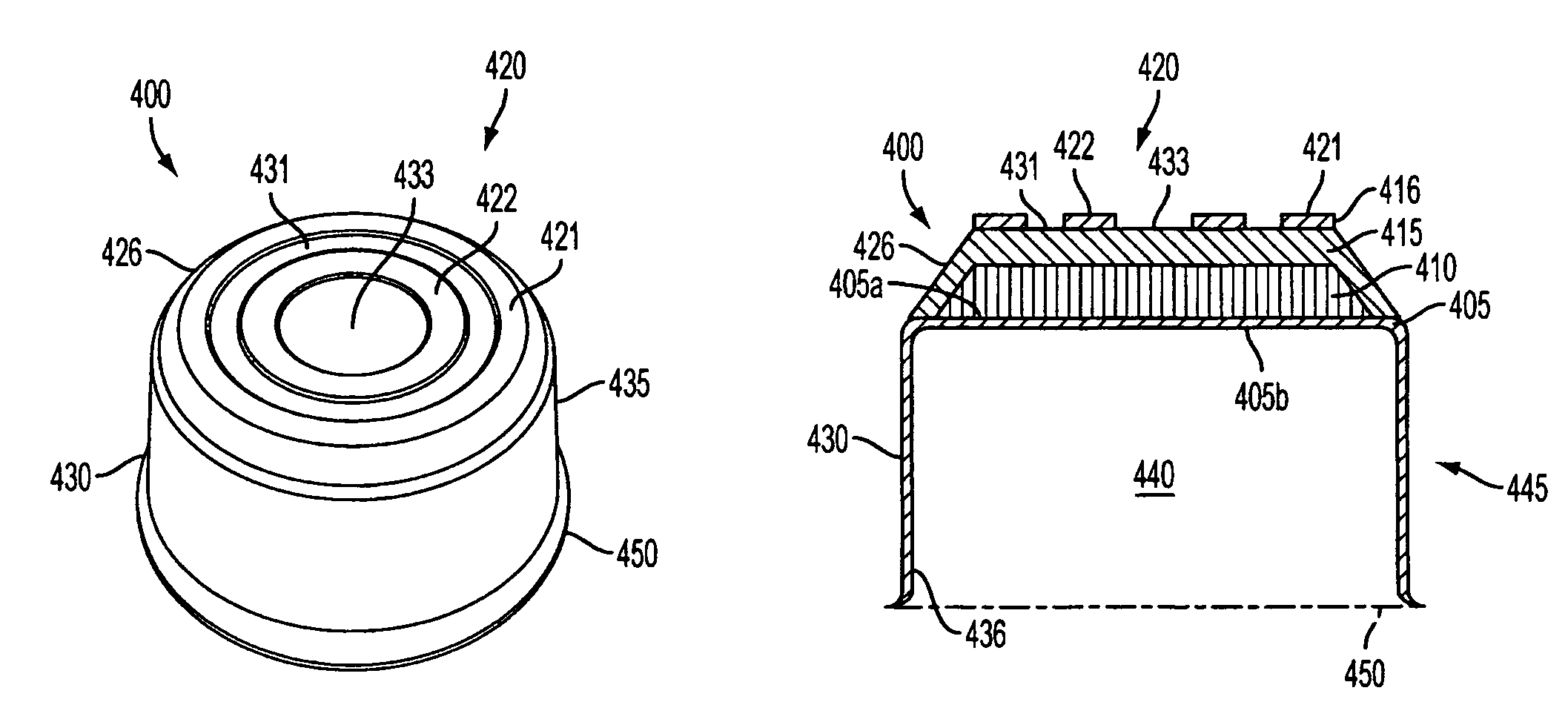
[0024]FIG. 4A is a prospective view of the bottom surface of a cooking vessel 400 according to the invention. Cooking vessel 400 has a circular bottom portion 420 surrounded by substantially upright wall 430 connected at the periphery thereof FIG. 4A shows the outside portion 435 of wall 430 whereas FIG. 4B shows the inner portion 436 of wall 430 which define an inner fluid retaining cavity 440. Cavity 440 extends from the inside bottom 421 of the vessel to rim 450, which flairs outward at the unconnected end of wall 430. Wall 430 and bottom 405 that define cavity 440 are integral to a vessel portion 445, whereas the remainder of the bottom 420 of vessel 400 is formed by adjacent layers 410, 415 and 416 with layer 410 being disposed in contact with the outer surface 405a of bottom 406 of vessel portion 445. FIG. 4B also displays the laminar construction of bottom portion 420, starting from inner or cooking surface 405b, layer 410, which is preferably aluminum, or a suitable alloy th...


PUM


Abstract

A cooking vessel is formed with one or more annular rings rising above a laminate structure that exposes at least one more thermally conductive material of a contrasting color. The raised rings reveal the nature of the thermally conductive material, yet protect it from scratches and abrasion during use, such as when the cooking vessel is resting on a stove top.

Description

CROSS REFERENCE TO RELATED APPLICATIONS[0001]NoneBACKGROUND OF INVENTION[0002]The present invention relates to improve cooking vessels, in particular those having more durable wear resistant bottom surfaces.[0003]Cooking vessels, such as pots and pans, are constructed out of a wide variety and combinations of metals as well as non-metallic coatings. Certain materials are selected for their heat transfer properties, while others are deployed as external surfaces, and frequently selected to improve durability in that they offer a consistent external appearance, despite the propensity for scratching or marring that occurs from contact with heating elements during use, stirring utensils or cleaning agents.[0004]Copper in particular is a favorite material for constructing cooking vessels, because of its unique appearance, but also for its superior heat transfer properties compared to other metals. A popular design for cooking vessels is to utilize a laminate construction in which a layer...

Claims


Application Information

Patent Timeline
Patent Type & Authority Patents(United States)
IPC IPC(8): A47J27/00A47J36/00
CPCA47J27/002
Inventor CHENG, STANLEY KIN SUITARENGA, ROBERTO
Owner MEYER INTPROP
Why Eureka
Try Eureka