Secure equipment rack door assembly

a technology for equipment racks and doors, applied in the field of secure equipment racks, can solve the problems of unauthorized access, damage to equipment and related cabling, vandalism, etc., and achieve the effect of convenient mounting and removal

Inactive Publication Date: 2006-12-26
TARASEWICZ MATTHEW J
View PDF13 Cites 47 Cited by
  • Summary
  • Abstract
  • Description
  • Claims
  • Application Information

AI Technical Summary

Benefits of technology

[0005]One aspect of the present invention relates to at least, but is not limited to, one door which may be comprised of, but is not limited to, a solid metal structure with ventilation holes or durable plastic or a combination of both. The door generally comprises a first and second side, whereby the first side includes a plurality of hinge posts, and the second side may or may not include at least, but is not limited to, one secure fastening mechanism. The door is easily mountable and removable from the system in an open position by selectively inserting or removing the above mentioned hinge posts into or out of the slotted hinge apertures of the mounting brackets of the present invention.

Problems solved by technology

This has left both the equipment and related cabling prone to damage, vandalism, and access by unauthorized personnel.
With respect to this need of increased security and manageability, businesses are faced with the difficult decision between the extremely costly move of their existing network infrastructure to a more secure environment, or accepting a lower level of security and manageability by doing nothing at all.

Method used


Image

  • Secure equipment rack door assembly
  • Secure equipment rack door assembly
  • Secure equipment rack door assembly

Examples


Embodiment Construction

[0025]Access to a secure equipment rack door assembly may be controlled by the type of locking mechanism used to secure the eyeholes of both the door and the secure fastening mechanism. A locking mechanism may comprise, but is not limited to, a combination lock, a padlock, or some similar device, thereby restricting access to only those individuals who have a special key or know the correct combination.

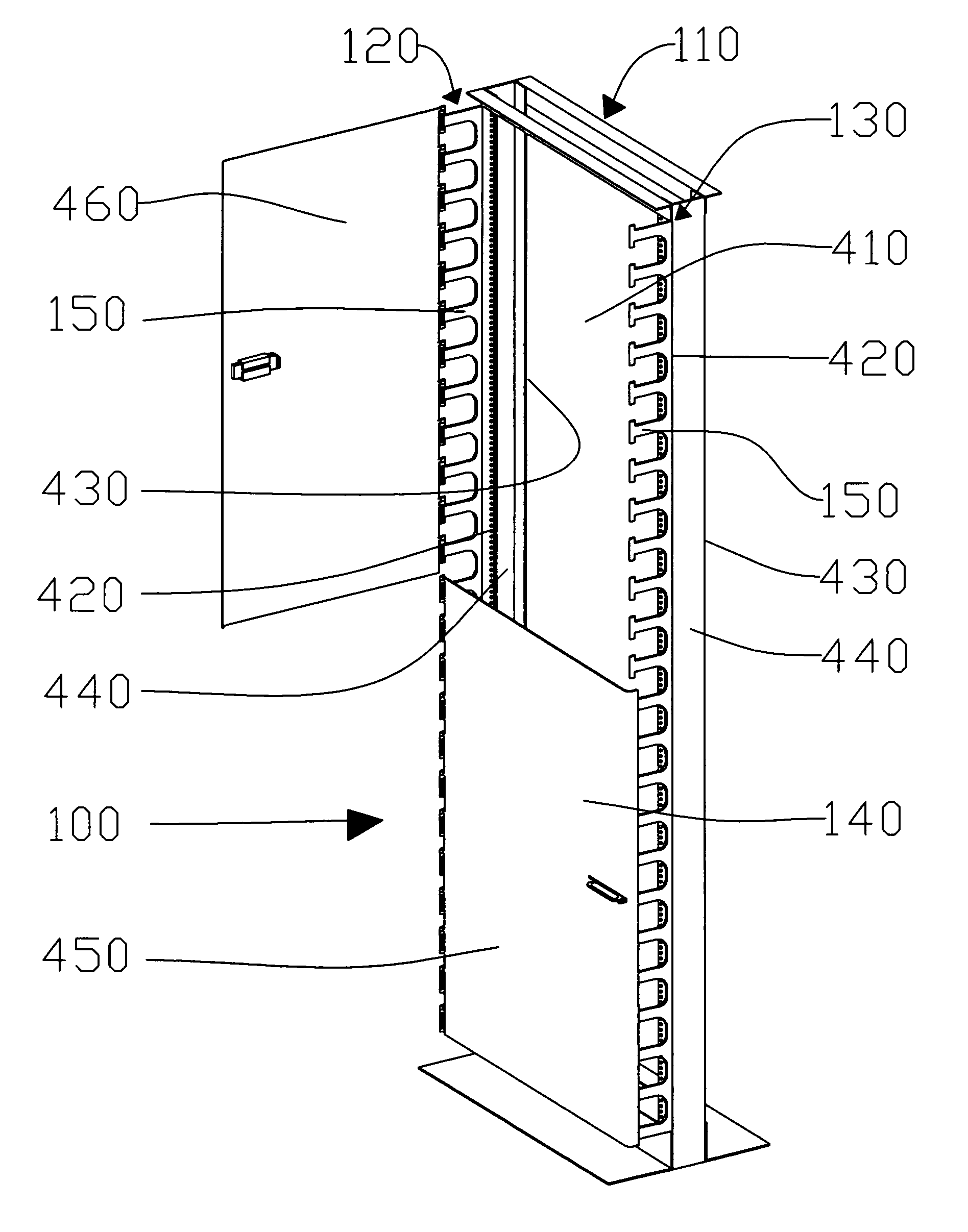
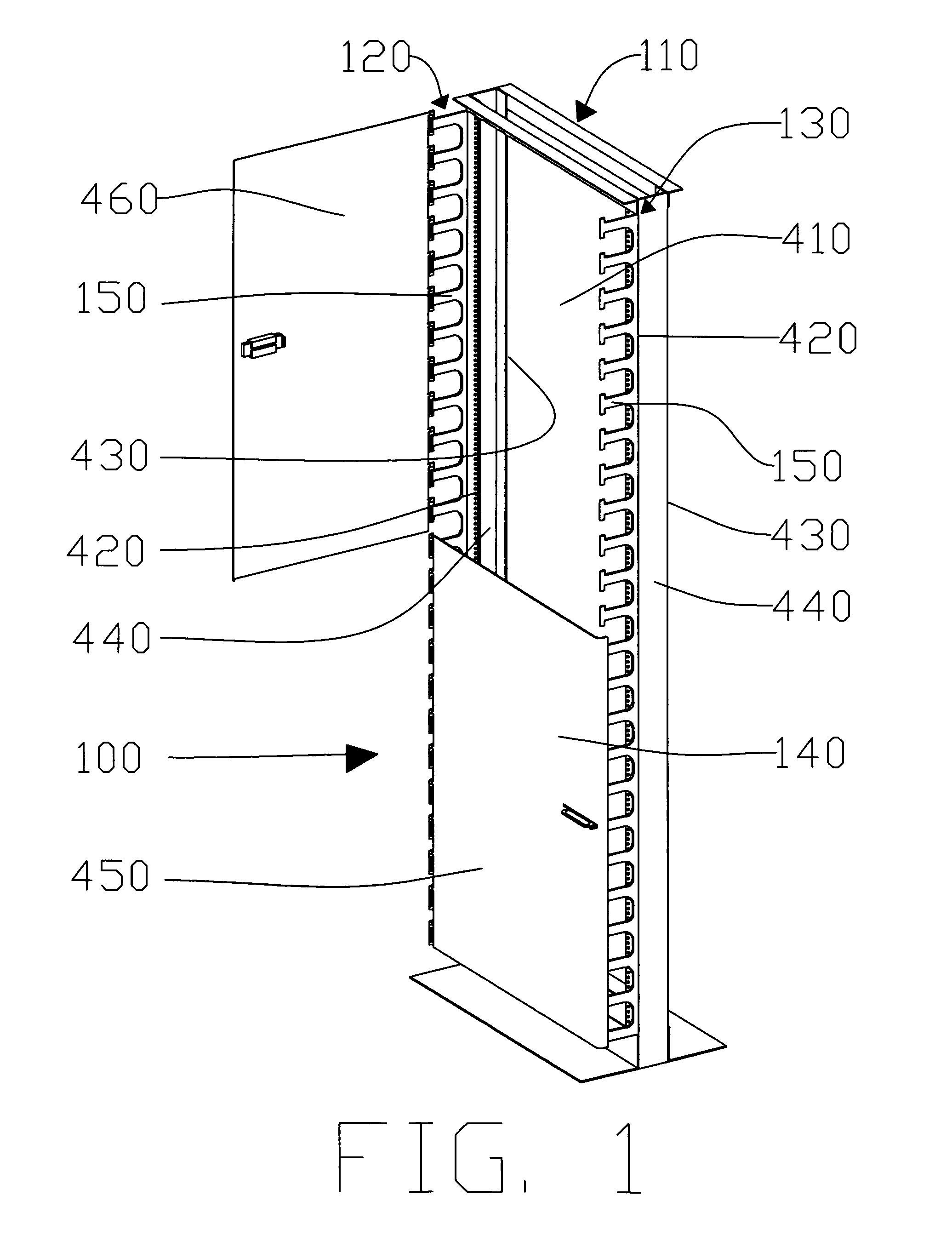
[0026]FIG. 1 depicts a preferred embodiment of the present invention, wherein a secure equipment rack door assembly 100 is attached to a standard network equipment rack 110 in accordance with the present invention. The two identical vertical rails 440 of a standard network equipment rack 110 each generally comprise an identical front face 420 and rear face 430. The secure equipment rack door assembly 100 is designed to attach to either the front face 420 or rear face 430 of a standard network equipment rack 110. The secure equipment rack door assembly 100 defines a cavity 410 defined ...


PUM


Abstract

A secure equipment rack door assembly is disclosed including a door, a secure fastening mechanism, and two identical brackets mountable to an existing telecommunications equipment rack. The mounting brackets are vertically fastenable to a telecommunications equipment rack using the existing rack dress screws and mounting holes distributed along the side rails of the telecommunications equipment rack. The mounting brackets further include a plurality of cable management fingers and hinge apertures. The hinge apertures of the mounting brackets are designed to accept a plurality of hinge posts located along a first side of the door, thusly allowing the door to be pivotably moveable relative to the mounting bracket. The hinge apertures further include a vertical slot which may accept the deadbolt portion of the secure fastening mechanism which may be located along a second side of the door.

Description

BACKGROUND OF THE INVENTION[0001]In the telecommunications industry, network equipment racks are widely used to hold and manage computer networking equipment, cabling, and related interconnects. Network equipment racks typically comprise a frame wherein a plurality of electronic components or connector locations including, but not limited to, copper cabling, fiber optics, network switching gear, and network servers, may be mounted.[0002]Traditionally, ease of use and accessibility has been a priority regarding the cabling and equipment housed within network equipment racks. Network equipment racks are often located in accessible areas, such as basements, closets, and mechanical rooms. This has left both the equipment and related cabling prone to damage, vandalism, and access by unauthorized personnel. As the cost of computer networking equipment rises, and as businesses are realizing how proper management and securement of the interconnects between the equipment and the associated c...

Claims


Application Information

Patent Timeline
Patent Type & Authority Patents(United States)
IPC IPC(8): A47B81/00A47B91/00A47B97/00
CPCE05C1/04H04Q1/062H04Q1/09E05B67/383E05Y2900/208
Inventor TARASEWICZ, MATTHEW JOHN
Owner TARASEWICZ MATTHEW J
Why Eureka
Try Eureka