Termination structure of cable with shield layer

a technology of termination structure and shield layer, which is applied in the direction of cable termination, connection contact member material, coupling device connection, etc., can solve the problems of high production cost and fear of damaging the insulation layer, and achieve the effect of reducing cos

Active Publication Date: 2006-12-26
HITACHI METALS LTD
View PDF8 Cites 22 Cited by
  • Summary
  • Abstract
  • Description
  • Claims
  • Application Information

AI Technical Summary

Problems solved by technology

There are, however, such problems that the above-mentioned termination structure 55 is composed of a large number of parts, and a yield thereof cannot be increased because the housing 61 is manufactured by means of matched-mold forming, resulting in high production costs.
As a result, there is a fear of damaging the insulation layer 52 being electrically important.

Method used


Image

  • Termination structure of cable with shield layer
  • Termination structure of cable with shield layer
  • Termination structure of cable with shield layer

Examples


first embodiment

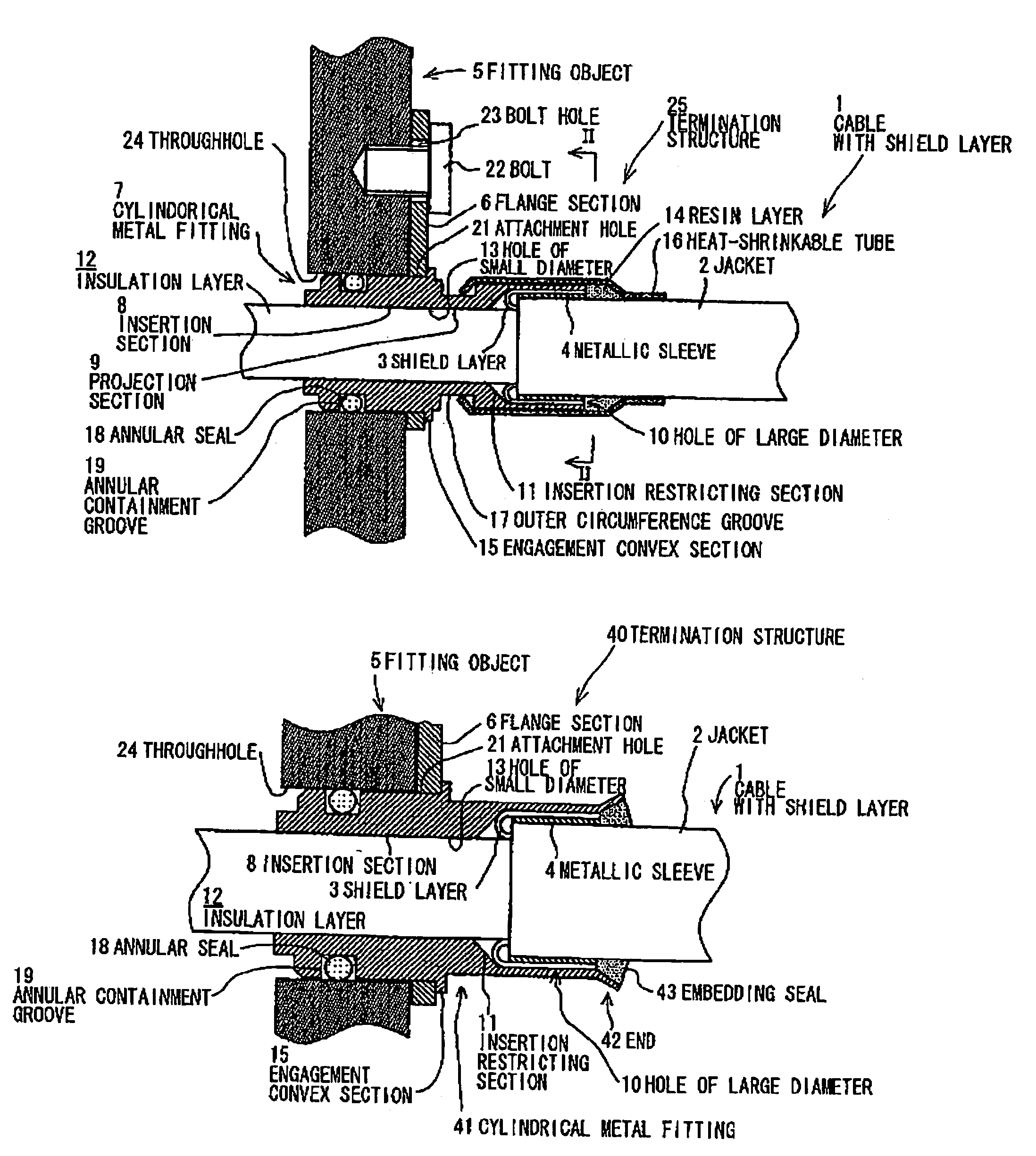
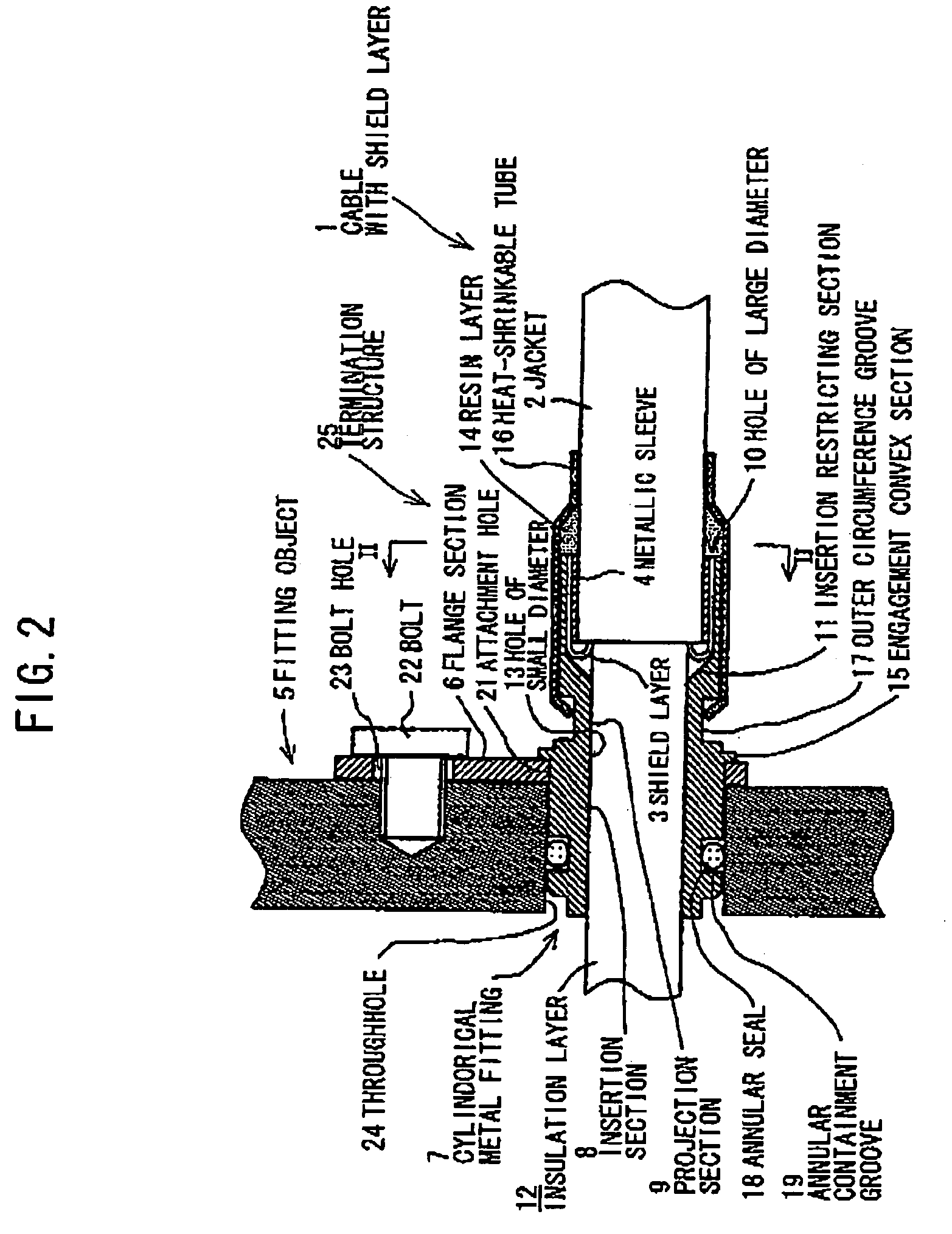
[0034]FIG. 2 is a cross sectional view showing a termination structure of a cable with a shield layer in the first preferred embodiment according to the present invention. FIG. 3 is a cross sectional view cut along the line II—II in FIG. 2.

[0035]As shown in FIGS. 2 and 3, an jacket 2 is cut way to be removed from an end of a cable 1 with a shield layer, so that the shield layer 3 is exposed from beneath the jacket 2. The jacket 2 is covered with a metallic sleeve 4. The metallic sleeve 4 is formed into a cylindrical configuration having a predetermined length in the axial direction, and has an inside diameter which is fitted firmly to the jacket 2 with substantially no clearance when the cable 1 with the shield layer is inserted thereinto.

[0036]The shield layer 3 exposed from beneath the jacket 2 cut away is folded back at an end position of the jacket 2 to cover the outer circumference of the metallic sleeve 4. More specifically, the shield layer 3 is turned over at a turning-back ...

second embodiment

[0061]FIG. 6 is a cross sectional view showing a termination structure of a cable with a shield layer in the second preferred embodiment according to the present invention. In FIG. 6, like components are indicated by the same numerals as used in FIG. 2.

[0062]A termination structure 40 of a cable 1 with a shield layer shown in FIG. 6 is a type wherein a seal structure between the above-mentioned cylindrical metal fitting 7 and the jacket 2 is modified to use no heat-shrinkable tube 16. It is to be noted that the same constitutions and functions as those of the above-mentioned embodiments are represented by the same reference numerals as that of the above-described figures in FIG. 6, and the explanation therefor will be omitted.

[0063]As shown in FIG. 6, an jacket 2 is cut away from an end of the cable 1 with the shield layer, so that the shield layer 3 is exposed from beneath the jacket 2. The jacket 2 of the cable 1 with the shield layer is covered with a metallic sleeve 4, and the o...


PUM


Abstract

A termination structure of a cable with a shield layer wherein a part of a jacket of the cable is removed at an end of the cable to expose a part of the shield layer and the exposed part of the shield layer is grounded to a fitting object and the cable is fitted in water-tightness with the fitting object. The termination structure has: a metallic sleeve disposed on the jacket of the cable, the metallic sleeve being covered with the exposed part of the shield layer being folded at an end of the jacket; a cylindrical metal fitting being disposed on the periphery of the folded shield layer and swaged at a fixing section corresponding to the folded shield layer to fix the cable; and a heat-shrinkable tube disposed on the periphery of the cylindrical metal fitting and the jacket.

Description

[0001]The present application is based on Japanese patent application No. 2003-191130, the entire contents of which are incorporated herein by reference.BACKGROUND OF THE INVENTION[0002]1. Field of the Invention[0003]The present invention relates to a method for fabricating a termination structure of a cable with a shield layer to be connected to electrical instruments which are constituted in water-tightness such as a battery, an inverter, and a motor in an electric vehicle.[0004]2. Description of the Related Art[0005]As a termination structure of a cable with a shield layer which is wired between a battery and an inverter, or an inverter and a motor in an electric vehicle, the one described in Japanese patent application laid-open No. 2001313100 is known.[0006]As shown in FIG. 1, a cable 50 with a shield layer is prepared by overlaying successively a core wire 51, an insulation layer 52, a shield layer 53, and an jacket 54 one another in this order. A termination structure 55 of t...

Claims


Application Information

Patent Timeline
Patent Type & Authority Patents(United States)
IPC IPC(8): H01R13/648
CPCH01R9/0524Y10S439/932
Inventor SHIMIZU, MICHIAKISATO, NOBORUITO, SHINJIYAMASHITA, NOBUYUKI
Owner HITACHI METALS LTD
Why Eureka
Try Eureka