Electric-motored floor-surface polisher

a technology of floor surface polisher and motor, which is applied in the direction of carpet cleaner, instruments, photosensitive materials, etc., can solve the problems of large drive noise, and insufficient or irregular work, and achieves smooth and efficient driving, increased working area, and efficient operation

Inactive Publication Date: 2007-01-02
PENGUIN WAX
View PDF9 Cites 17 Cited by
  • Summary
  • Abstract
  • Description
  • Claims
  • Application Information

AI Technical Summary

Benefits of technology

[0031]According to the characterizing feature of the invention relating to claim 1 or 3, the pad, even if formed large to have an increased working area, can act on the floor surface over the entire area thereof and at an equal speed. In addition, even if the moving stroke of the pad is increased, the pad can still be driven smoothly and efficiently, thus achieving efficient operation providing good finish while restricting occurrence of such problem as leaving any floor portion unpolished. And, the reaction forces acting on the pair of pads are effectively offset each other, thus causing less vibration in the apparatus frame, and with the reduced vibration in the pads, generation of driving noise can be effectively restricted. As a result, the apparatus can operate silently. Moreover, even if the apparatus is constructed as a hand-propelled type, the apparatus will less likely “jump” up against the floor surface and the apparatus can be operated comfortably and easily even when the apparatus is supported only lightly by the operator's hands.
[0032]According to the characterizing feature of the invention relating to claim 2, distortion or twist between the pad and its supporting member is less likely to occur and the pad can be driven and reciprocated smoothly. In this case too, generation of vibration or noise can be effectively reduced and the apparatus can be operated quietly and comfortably.

Problems solved by technology

For this reason, even if the pad acts on the floor surface at an appropriate speed in its outer peripheral portion, the pad fails to provide sufficient polishing effect at the center portion thereof.
Especially, such insufficient or irregular work would occur more likely when the pad is formed large to provide an increased working area.
Then, even if this pad is formed large, such insufficient or irregular work will less likely to occur even for the enlarged working area of the pad.
Also, since the power transmission is effected by means of meshing of the gears, a large drive noise would be generated.
With this driving technique, since the pads are pivoted via the anti-vibration rubber elements as the pivots, there would occur vibrations such as vertical vibrations of the pads.
Further, if the moving stroke of the pad is to be increased, this will necessitate increase in the deformation amount at the pivot.
However, with such large deformation at the pivot, there will occur resistance against the movement of the pivot due to the load for pressing the pad against the floor surface.
As a result, a driving problem or failure would tend to occur.
In view of this, it was actually not possible to secure such a large movement stroke for the pad.

Method used


Image

  • Electric-motored floor-surface polisher
  • Electric-motored floor-surface polisher
  • Electric-motored floor-surface polisher

Examples


first embodiment

[First Embodiment]

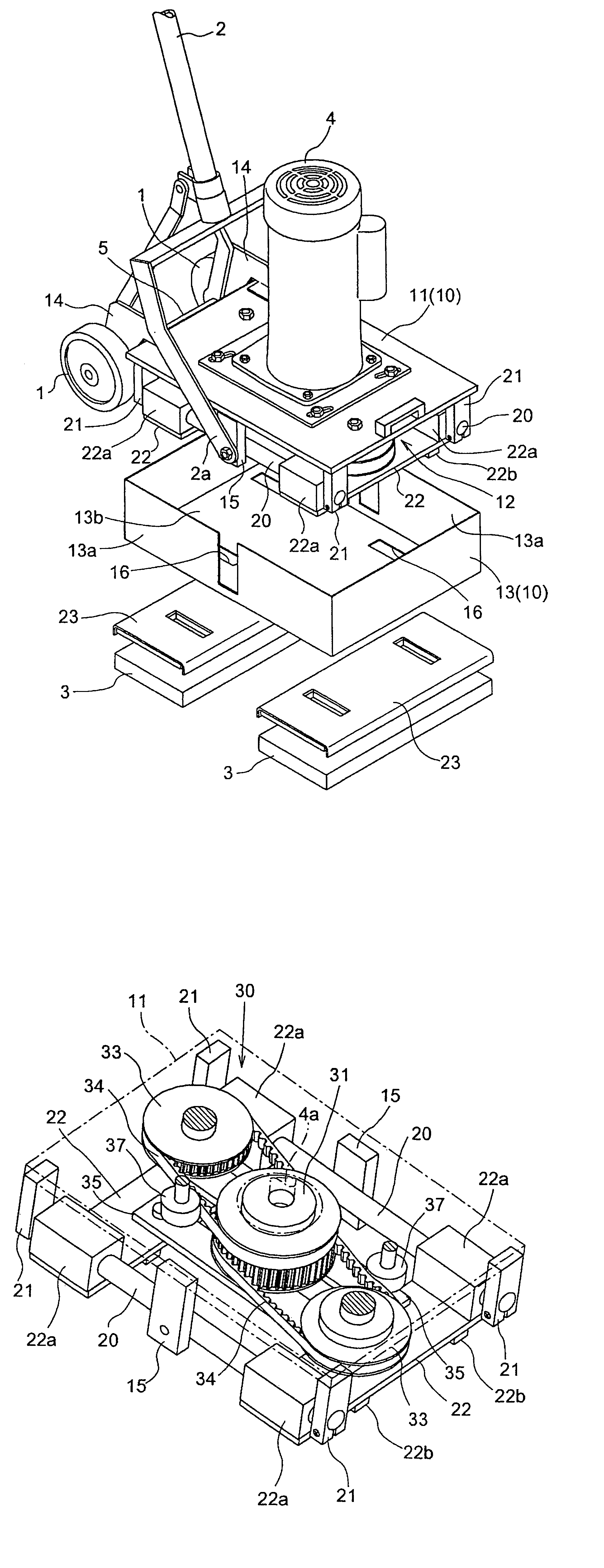
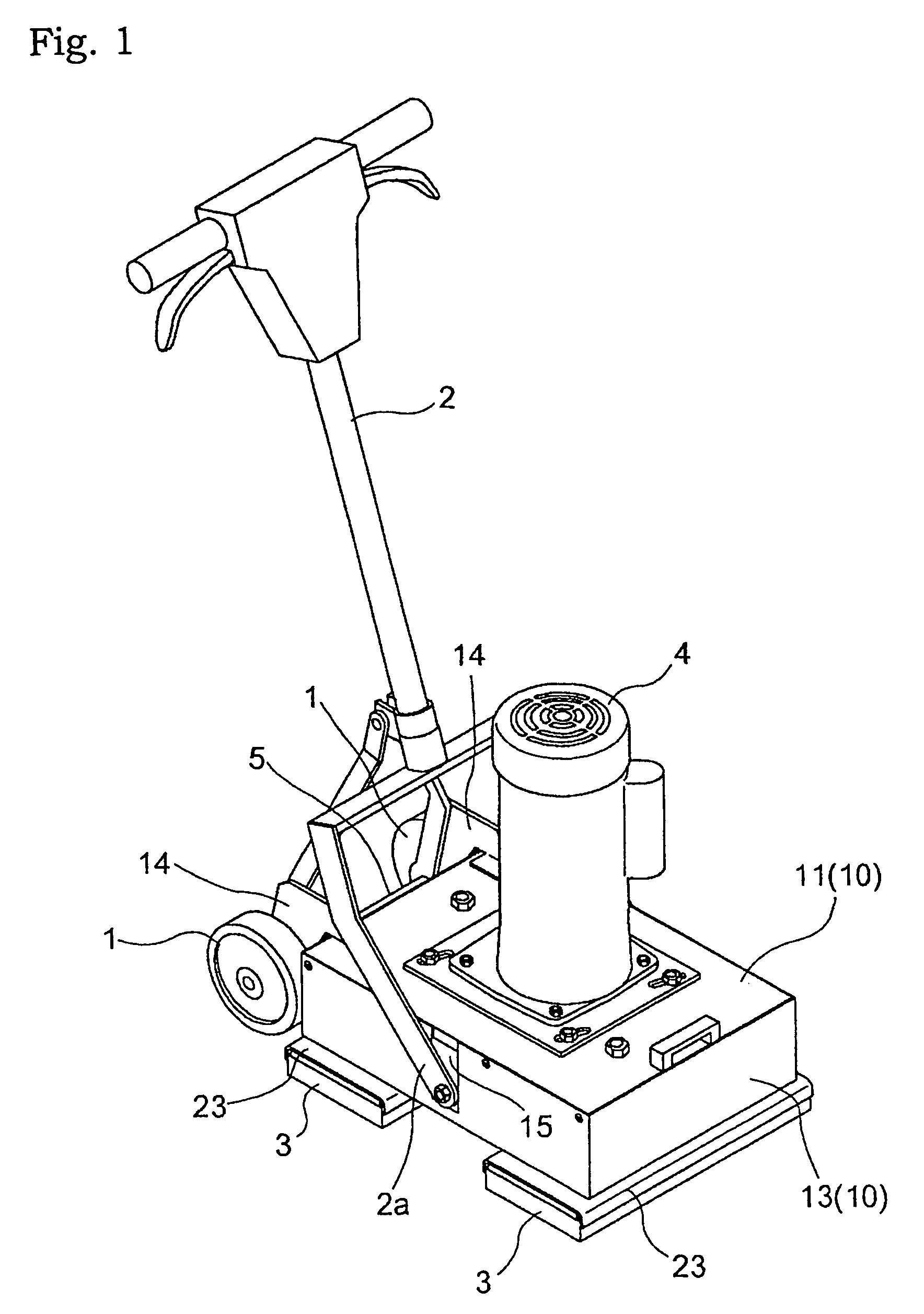
[0043]As shown in FIG. 1, a hand-propelled compact electric-motored floor-surface polisher includes a pair of right and left free-rotation wheels 1, a machine frame 10 including a steering handle 2, a pair of pads 3 provided under the machine frame 10 and juxtaposed in the front and rear direction of the machine frame 10, and an electric motor 4 mounted on the top face of the machine frame 10.

[0044]With this polisher, in response to an operation or manipulation of the steering handle 2, the machine frame 10 can be pivoted upward at the front end portion thereof about the axle so as to lift the two pads 3 off the floor surface and under this condition, the machine can be transported to a work site by using the wheels 1. At the work site, the pair of pads 3 will be placed on the floor surface so that the entire load of the polisher may be applied to the pads 3. Under this condition, the pads 3 are driven by the electric motor 4 for polishing the floor surface of the ...

second embodiment

[Second Embodiment]

[0066]FIG. 8 shows a pad operating mechanism 30 employed in an electric-motored floor-surface polisher relating to the second embodiment of the present invention. This electric-motored floor-surface polisher includes the same machine frame 10 and the same pad mounting construction as employed in the above-described polisher relating to the first embodiment and differs therefrom only in the pad operating mechanism 30. Therefore, only this pad operating mechanism 30 will be described next.

[0067]The pad operating mechanism 30 employed in the polisher relating to this second embodiment includes a pair of upper and lower eccentric rotary cams 38 rotatably attached to an end of the output shaft 4a of the electric motor 4 which end extends into the pad driving chamber 12, a pad operating rod 39 connecting between one of the pair of upper and lower eccentric rotary cams 38 and the front pad support member 22 and a further pad operating rod 39 connecting between the other ...


PUM


Abstract

An electric-motored floor-surface polisher includes a pair of pads juxtaposed in the front and rear or lateral direction of an apparatus frame, each pad being slidably supported to the apparatus frame. A drive pulley coupled to an output shaft of an electric motor to be rotated therewith. The polisher includes a pair of pad driving members, each pad driving member having an input pulley portion operably coupled with the drive pulley via a toothed belt and having also an output portion provided at a portion of the driving member offset from a rotational axis of the input pulley portion to be rotatable therewith and a pair of pad operating rods, one of the pair of pad operating rods having one end thereof pivotally coupled with the output portion of one of the pair of pad driving members and the other end thereof pivotally coupled with the one of the pair of pads and the other pad operating rod having one end thereof pivotally coupled with the output portion of the other pad driving member and the other end thereof pivotally coupled with the other pad. With this, the pair of pad operating rods slidably reciprocate the pair of pads along the juxtaposing direction thereof and in directions opposite to each other.

Description

TECHNICAL FIELD[0001]The present invention relates to an electric-motored floor-surface polisher including an electric motor and a pad driven by the motor to act on a floor surface.BACKGROUND ART[0002]When a pad is rotatably driven to act on a floor surface, there occurs a difference in the peripheral speed between the center portion and the outer peripheral portion of the pad. For this reason, even if the pad acts on the floor surface at an appropriate speed in its outer peripheral portion, the pad fails to provide sufficient polishing effect at the center portion thereof. Especially, such insufficient or irregular work would occur more likely when the pad is formed large to provide an increased working area. On the other hand, if the pad is driven to effect a reciprocal movement relative to the floor surface, such pad can act on the floor surface at an equal speed over the entire face thereof. Then, even if this pad is formed large, such insufficient or irregular work will less li...

Claims


Application Information

Patent Timeline
Patent Type & Authority Patents(United States)
IPC IPC(8): A47L11/12A47L11/284
CPCA47L11/12A47L11/4069A47L11/4036
Inventor MORITA, ISAOUEDA, YASUHIRO
Owner PENGUIN WAX
Why Eureka
Try Eureka