
Canning structure and manufacturing method thereof
a technology of ceramic honeycomb and manufacturing method, which is applied in the direction of physical/chemical process catalysts, lighting and heating apparatus, separation processes, etc., can solve the problems of uneconomic canning structure and easy cracking or chipping and achieve the effect of preventing chipping and cracking of ceramic honeycomb structur
- Summary
- Abstract
- Description
- Claims
- Application Information
AI Technical Summary
Benefits of technology
Problems solved by technology
Method used
Image

Examples
embodiment
[0076]A ceramic carrier (ceramic honeycomb structure) manufactured of cordierite, with a diameter of 106 mm, length of 114 mm, partition thickness of 0.03 mm, and 465 cells / cm2, was prepared. A non-intumescent ceramic fiber mat (“MAFTEC” (product name), manufactured by MITSUBISHI CHEMICAL CORPORATION) of 1,200 g per 1 m2 was further wrapped thereupon, as a holding material.
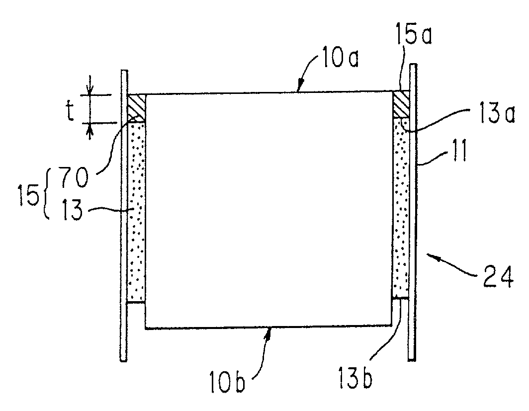
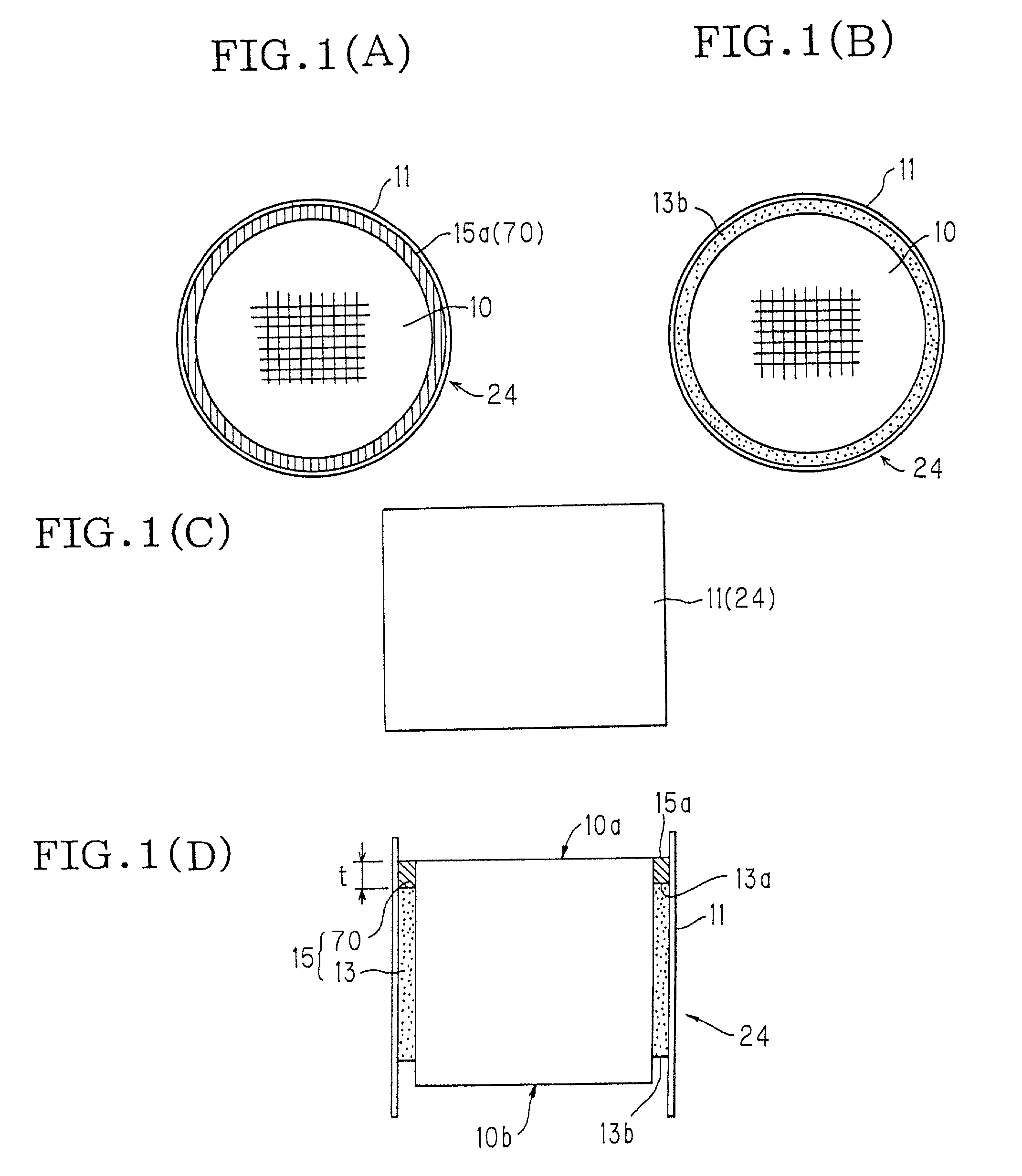
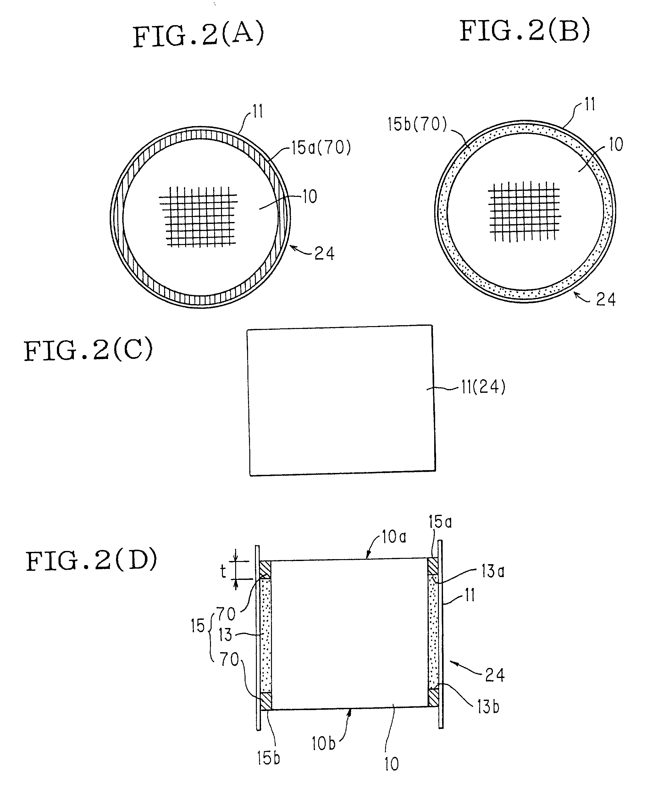
[0077]A rope-shaped impermeable member (material: polyethylene) was caused to adhere to one end 13a of the holding material in the longitudinal direction, thereby forming a ceramic honeycomb structure wrapped with a holding material having an impermeable layer 70 of 2 mm in length (see FIGS. 1A through 1D), which was pressed into a stainless-steel can (metal case) with an inner diameter of 114 mm, length of 124 mm, and thickness of 1.5 mm, using a tapered jig for pressing.
[0078]Next, twenty of such canning structures obtained with the embodiment were placed in the ceramic honeycomb catalytic converter manufacturin...
PUM
| Property | Measurement | Unit |
|---|---|---|
| temperature | aaaaa | aaaaa |
| length | aaaaa | aaaaa |
| partition thickness | aaaaa | aaaaa |
Abstract
Description
Claims
Application Information