
In the ear hearing aid utilizing annular ring acoustic seals

a technology of annular rings and acoustic seals, which is applied in the direction of deaf-aid sets, ear supports, electrical devices, etc., can solve the problem of not being able to locate the hearing aid instrument, and achieve the effect of reducing the power required, improving battery life, and lowering the natural frequency of the hearing aid

Inactive Publication Date: 2007-01-16
HEARING SPECIALTIES
View PDF33 Cites 66 Cited by
  • Summary
  • Abstract
  • Description
  • Claims
  • Application Information

AI Technical Summary

Problems solved by technology

In the second configuration the transmitter is located near the bony portion of the ear canal, since in some cases it is not possible to locate the hearing aid instrument in the bony portion of the patient's ear canal.

Method used


Image

  • In the ear hearing aid utilizing annular ring acoustic seals
  • In the ear hearing aid utilizing annular ring acoustic seals
  • In the ear hearing aid utilizing annular ring acoustic seals

Examples


Embodiment Construction

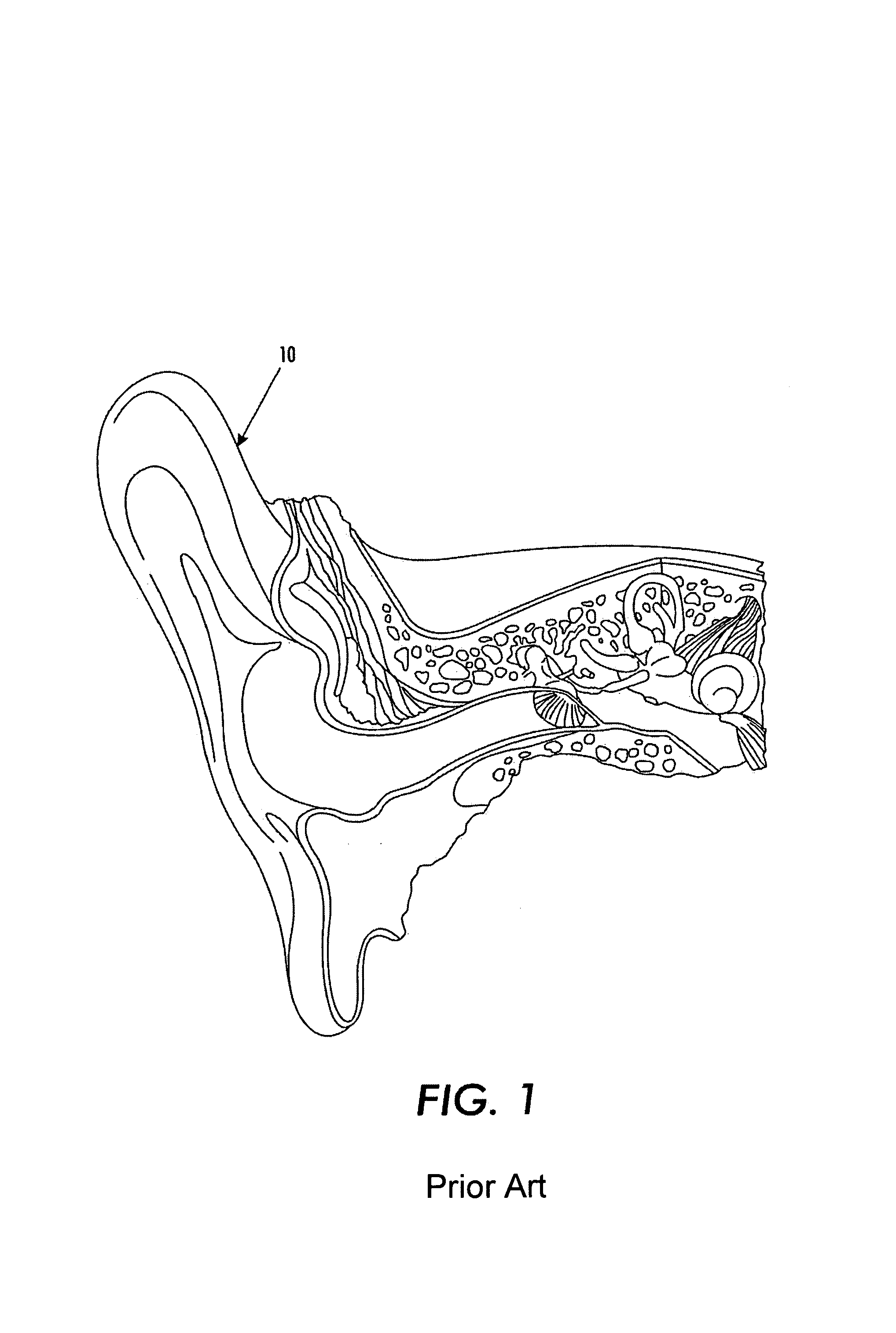
[0049]FIG. 1 is a sectional view of an ear 10 of a human being. This sectional view of the ear 10 is taken from “The Anatomy Chart Series,” Classic Library Edition, ISBN 0-9603730-4-7, Lb. Cat No. 86-071078, Page 21. In the embodiment depicted, the ear 10 is a right ear.

[0050]Reference also may be had, e.g. FIG. 1 of U.S. Pat. No. 6,228,020, which is “. . . a sectional elevational view of a user's hearing area to show the anatomy thereof.” The entire disclosure of such United States patent is hereby incorporated by reference into this specification.

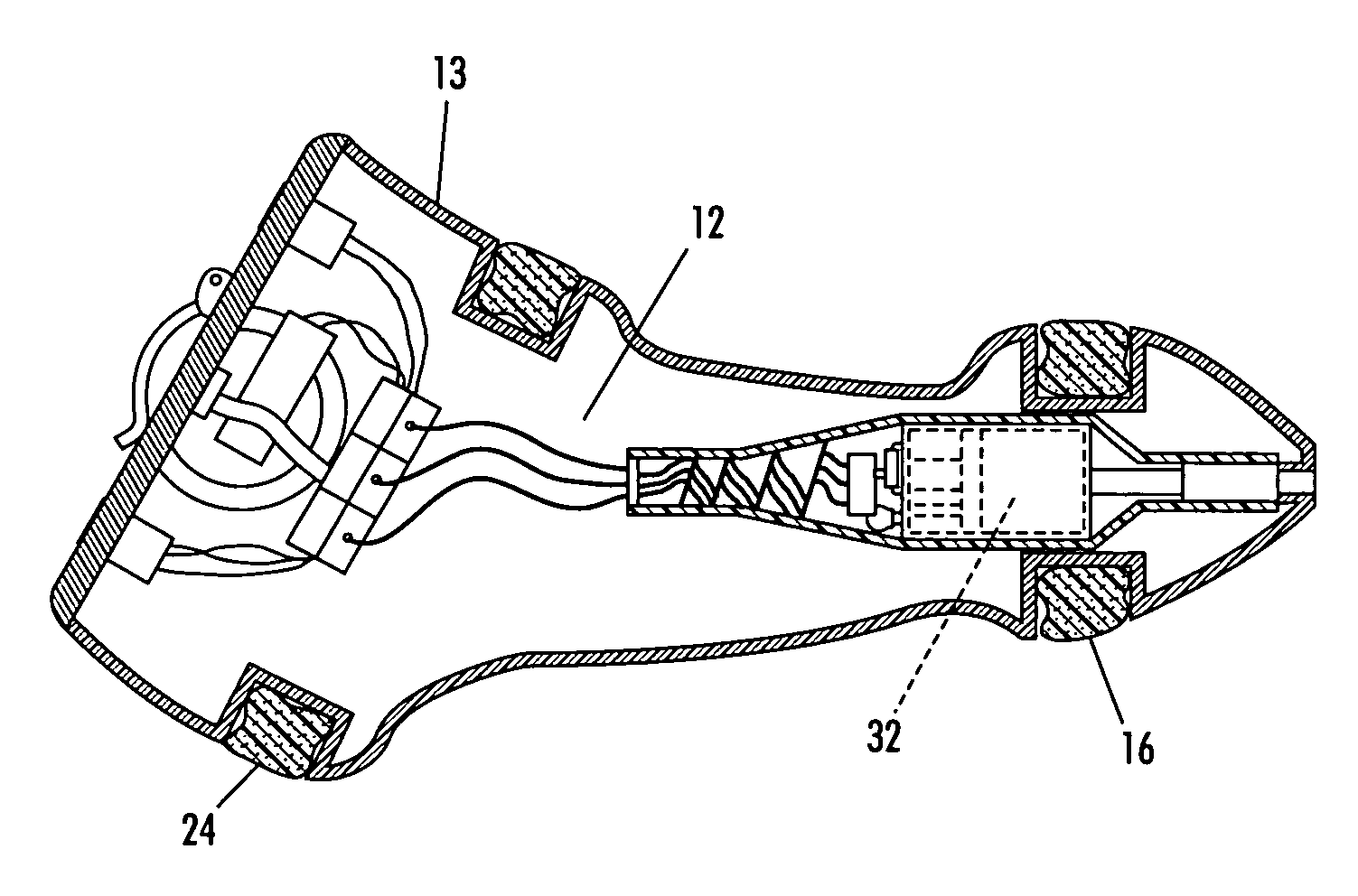
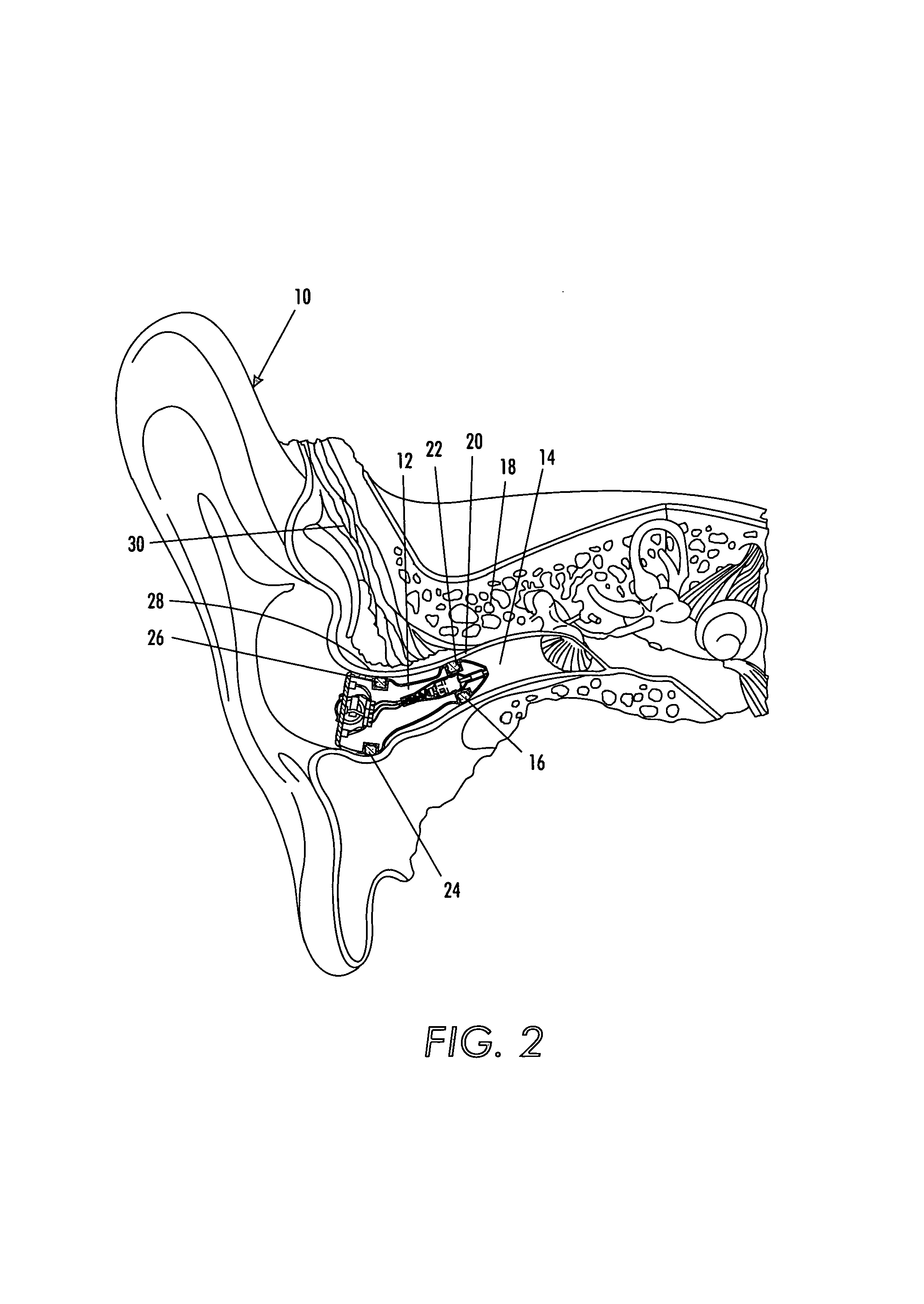
[0051]FIG. 2 is a sectional view of the ear 10 with a hearing aid assembly 12 disposed within the ear canal channel 14. The hearing aid assembly 12 is comprised of a first seal 16 that is disposed just prior to the bony portion 18 of the ear. In the embodiment depicted, the bony portion 18 starts at point 20. The distance between the end 22 of the first seal 16 and the point 20 is preferably no greater than about 2 millimeters and, more p...


PUM


Abstract

Disclosed is a hearing aid assembly wherein the hearing aid is comprised of an acoustic receiver, an acoustic transmitter, and a body, and an annular channel, wherein the acoustic receiver is designed to fit into a external acoustic meatus of an ear, the acoustic transmitter is designed to fit into a inner ear canal, and the generally cylindrical body is disposed between the receiver and the transmitter, the annular channel is disposed on the surface of the body such that it circumscribes the body's circumference. The annular channel is adapted to receive an annular ring which functions as an acoustic seal.

Description

CROSS-REFERENCE TO RELATED PATENT APPLICATIONS[0001]This application claims the benefit of U.S. provisional patent application 60 / 525,911 filed Dec. 1, 2003. The entire content of this patent application is hereby incorporated by reference into this specification.FIELD OF THE INVENTION[0002]A hearing aid assembly with a housing whose outer surface contains one or more annular channels within which are disposed one or more compliant acoustic material ring seals.BACKGROUND OF THE INVENTION[0003]Hearing aid assemblies are well known to those skilled in the art. By way of illustration and not limitation, reference may be had to U.S. Pat. No. 6,228,020 (compliant hearing aid), U.S. Pat. No. 6,438,244 (hearing aid construction with electronic components encapsulated in soft polymeric body), U.S. Pat. No. 6,473,512 (apparatus and method for a custom, soft-solid hearing aid), U.S. Pat. No. 6,434,248 (soft hearing aid molding apparatus), U.S. Pat. No. 6,432,247 (method of manufacturing a sof...

Claims


Application Information

Patent Timeline
Patent Type & Authority Patents(United States)
IPC IPC(8): H04R25/02H04R25/00
CPCH04R25/658H04R25/652B33Y80/00B33Y70/00
Inventor MEYER, JOHN A.MORABITO, ANDREW F.
Owner HEARING SPECIALTIES
Learn More