Modular tankless water heater control circuitry and method of operation

a water heater and control circuit technology, applied in the direction of fluid heaters, liquid transfer devices, lighting and heating apparatus, etc., can solve the problems of large volume of water, poor energy efficiency and water conservation, and difficulty in heating water accurately and efficiently in a consistent and safe manner

Inactive Publication Date: 2007-01-16
SKYE INT
View PDF3 Cites 58 Cited by
  • Summary
  • Abstract
  • Description
  • Claims
  • Application Information

AI Technical Summary

Benefits of technology

[0011]In a specific embodiment, control circuitry for a tankless water heater system is disclosed. The tankless water heater system includes a water heater module with four water conduits connected in series, the series connection being further connectable to a cold water supply and to provide a heated water flow to a heated water demand site. The control circuitry includes four water heater elements, one each associated with each of the plurality of water conduits. A controller in the control circuitry includes a CPU programmed with an operating program. A plurality of sensors are positioned in the water flow and electrically coupled to the controller with at least one of the plurality of sensors providing an indication of the water temperature in an outlet of the series connection. Connecting and operating circuitry couples each of the plurality of water heater elements to the CPU. The CPU is programmed to control the connecting and operating circuitry in accordance with indications from the plurality of sensors to individually activate a first water heater element to a first power level for a first heat required in response to a demand for heated water. For heat required greater than the first heat required and less than a second heat required in response to a demand for heated water the CPU increases the power level of the first water heater element in predetermined increments.
[0012]The CPU is programmed to control the connecting and operating circuitry in accordance with indications from the plurality of sensors to individually activate a second water heater element of the four water heating elements to the first power level for the second heat required. For heat required greater than the second heat required and less than a third heat required in response to a demand for heated water the CPU increases the power level of the second water heater element in predetermined increments. The CPU is also programmed to individually activate a third water heater element of the four water heater elements to the first power level for the third heat required. For heat required greater than the third heat required and less than a fourth heat required in response to a demand for heated water the CPU increases the power level of the third water heater element in predetermined increments. The CPU is also programmed to individually activate a fourth water heater element of the four water heater elements to the first power level for the fourth heat required. For heat required greater than the fourth heat required and less than a fifth heat required in response to a demand for heated water the CPU increases the power level of the fourth water heater element in predetermined increments.

Problems solved by technology

While effective, energy efficiency and water conservation can be poor.
This can often amount to a substantial volume of water.
However, heating water accurately and efficiently in a consistent and safe manner can be problematic with current tankless systems.
It is, for example, difficult and highly inefficient to heat water to a desired useable state each time hot water is used.
Applying full power to heating elements for short periods and randomly is very fatiguing on components and causes substantial wear and degradation.
Further, in many prior art types of water heaters the water is over heated, too much water is heated, or the water is heated above a maximum desired temperature all of which wastes power and adds to the eventual deterioration of the system.

Method used


Image

  • Modular tankless water heater control circuitry and method of operation
  • Modular tankless water heater control circuitry and method of operation
  • Modular tankless water heater control circuitry and method of operation

Examples


Embodiment Construction

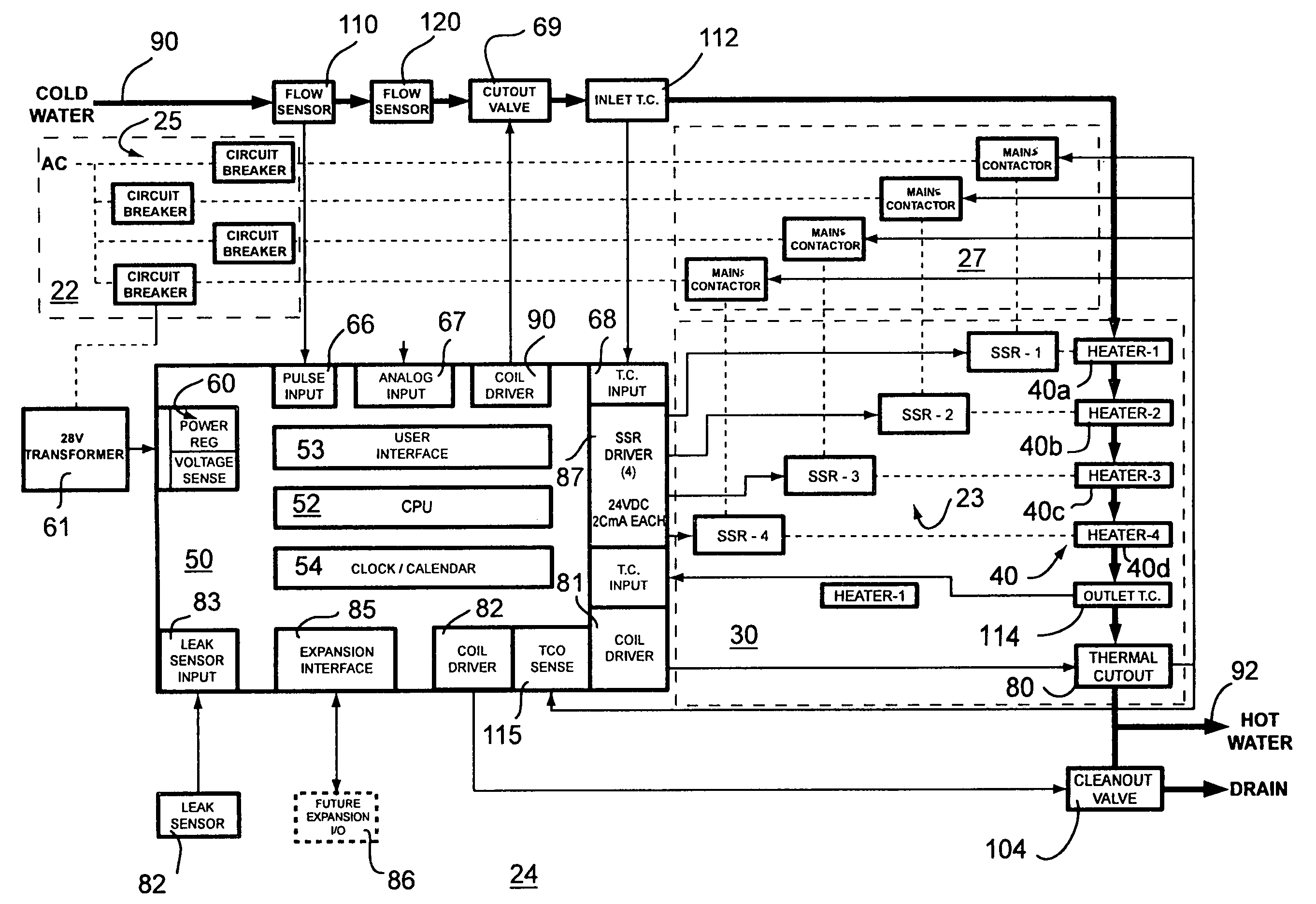
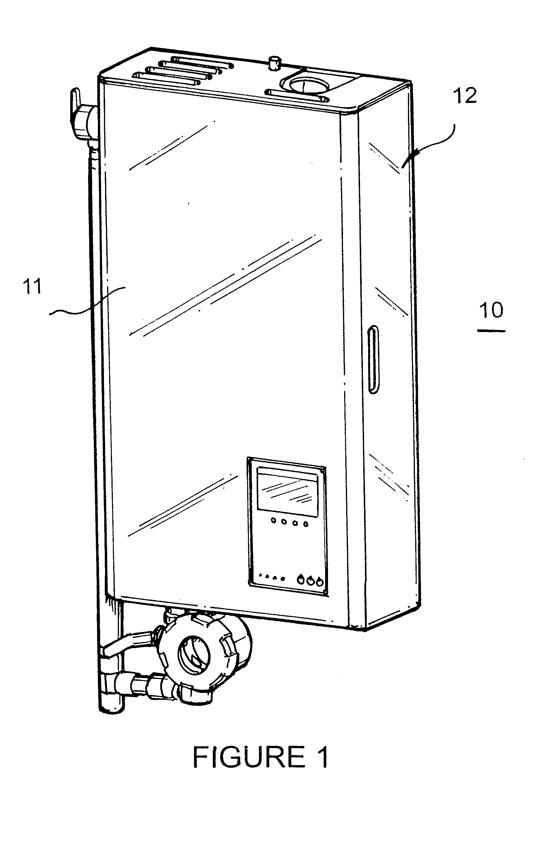
[0027]Turning now to the drawings in which like reference characters indicate corresponding elements throughout the several views, attention is directed to FIG. 1 which illustrates a tankless water heater system generally designated 10 that can be used in conjunction with the present control circuitry. Tankless water heater 10 is described in more detail in a copending United States Patent Application entitled “Modular Tankless Water Heater” filed of even date herewith and incorporated herein by reference. System 10 includes a housing 12 closed by a cover 11. Tankless water heater system 10 is a system which heats water as its flows through. Electrical power is conserved by heating water only as it is needed. As water needs are increased, increasing amounts of energy are added to the flowing water to reach a desired temperature.

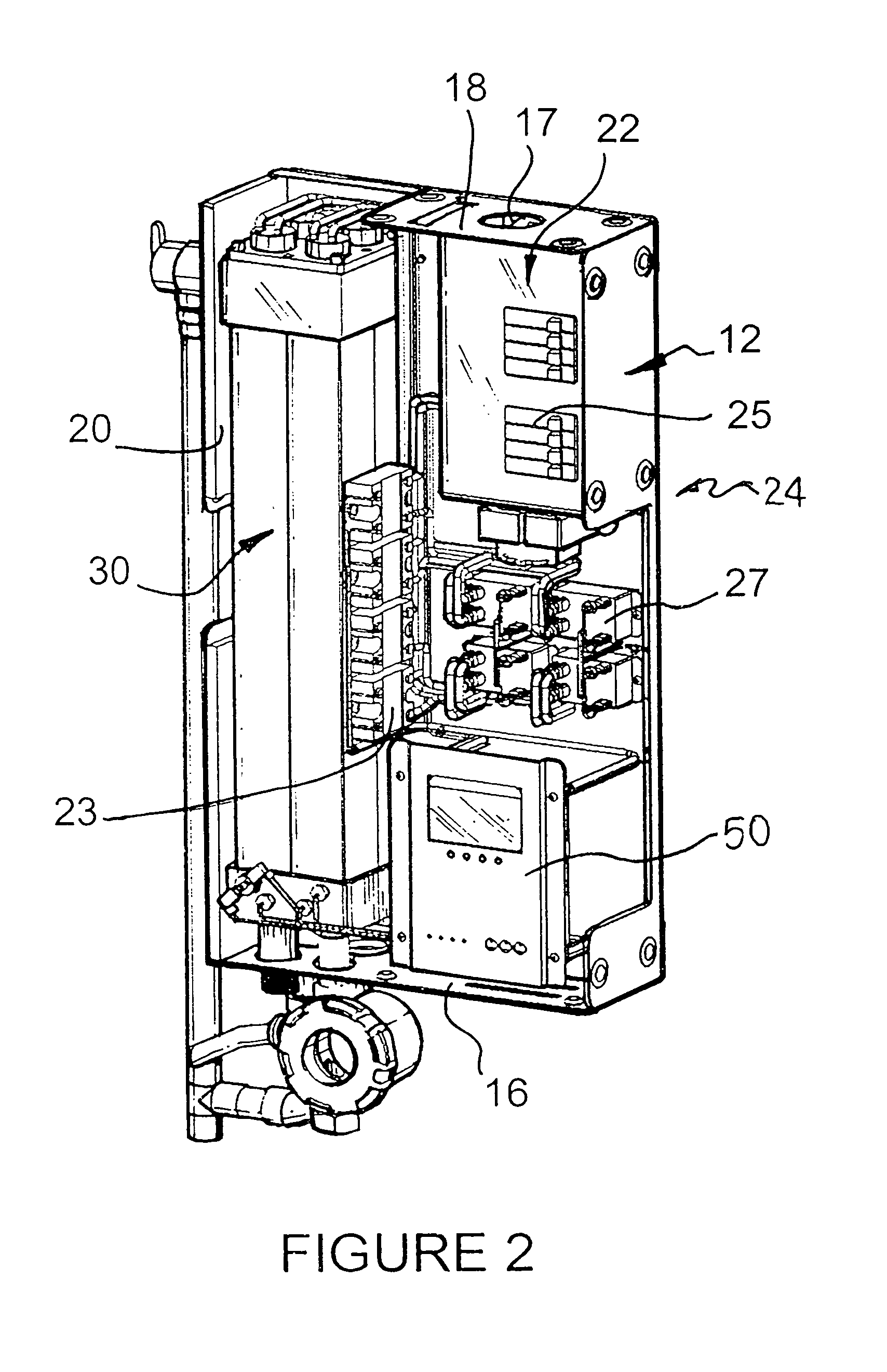
[0028]Referring to FIGS. 2 and 3, housing 12 acts as a support structure for the various components of system 10, and includes a flush aperture 13, an inlet ...


PUM


Abstract

Control circuitry is disclosed for use with a tankless water heater system including a plurality of water conduits connected in series. The control circuitry includes a plurality of water heater elements, one each associated with each of the plurality of water conduits. A controller includes a central processing unit (CPU) with an operating program and each of the plurality of water heater elements are coupled to the CPU. The CPU is programmed to individually activate one of the water heater elements to a predetermined power level in response to a demand for heated water. The number of water heater elements activated and the power level of the activation is determined by the demand for heated water.

Description

FIELD OF THE INVENTION[0001]This invention relates to water heater controls.[0002]More particularly, the present invention relates to controls for water heaters employing resistive heating elements.[0003]More particularly, the present invention relates to methods of operating a controller for water heaters.BACKGROUND OF THE INVENTION[0004]The need for heated fluids, and in particular heated water, has long been recognized. Conventionally, water has been heated by heating elements, either electrically or with gas burners, while stored in a tank or reservoir. While effective, energy efficiency and water conservation can be poor. As an example, water stored in a hot water tank is maintained at a desired temperature at all times. Thus, unless the tank is well insulated, heat loss through radiation can occur, requiring additional input of energy to maintain the desired temperature. In effect, continual heating of the stored water is required. Additionally, the tank is often positioned at...

Claims


Application Information

Patent Timeline
Patent Type & Authority Patents(United States)
IPC IPC(8): F24H9/20
CPCF24H9/2028F24H15/128F24H15/238F24H15/156F24H15/429F24H15/31F24H15/12F24H15/37F24H15/219F24H15/148F24H15/172F24H15/407F24H15/174F24H15/215
Inventor STURM, WILLIAM R.SULLIVAN, JOSEPH M.SHORTLAND, THOMAS J.HAY, KEVINJOHNSON, GREGG C.
Owner SKYE INT
Why Eureka
Try Eureka