
Rotary drill bit having cutting insert with a notch

a rotary drill bit and cutting insert technology, applied in the field of excavating tools, can solve the problems of unsupported roof of tunnel, increased risks of underground coal mining, unsupported roof,

Active Publication Date: 2007-01-30
KENNAMETAL INC
View PDF24 Cites 22 Cited by
  • Summary
  • Abstract
  • Description
  • Claims
  • Application Information

AI Technical Summary

Problems solved by technology

Initially, this tunnel has an unsupported roof.
Because the roof is not supported, there is an increased chance for a mine cave that, of course, adds to the hazards of underground coal mining.
Furthermore, an unsupported roof is susceptible to rock and debris falling from the roof.
Falling rock and debris can injure workers as well as create hazardous clutter on the floor of the tunnel.
Roof bolting accounts for the largest number of lost time injuries in underground mining.
During the roof bolting process, the roof is unsupported so that it does not have optimum stability.
Furthermore, the roof bolting process exerts stresses on the roof so as to further increase the safety hazards during the roof bolting process.
Thus, a decrease in the overall time necessary to bore holes reduces the time it takes to complete the roof bolting process.

Method used


Image

  • Rotary drill bit having cutting insert with a notch
  • Rotary drill bit having cutting insert with a notch
  • Rotary drill bit having cutting insert with a notch

Examples


Embodiment Construction

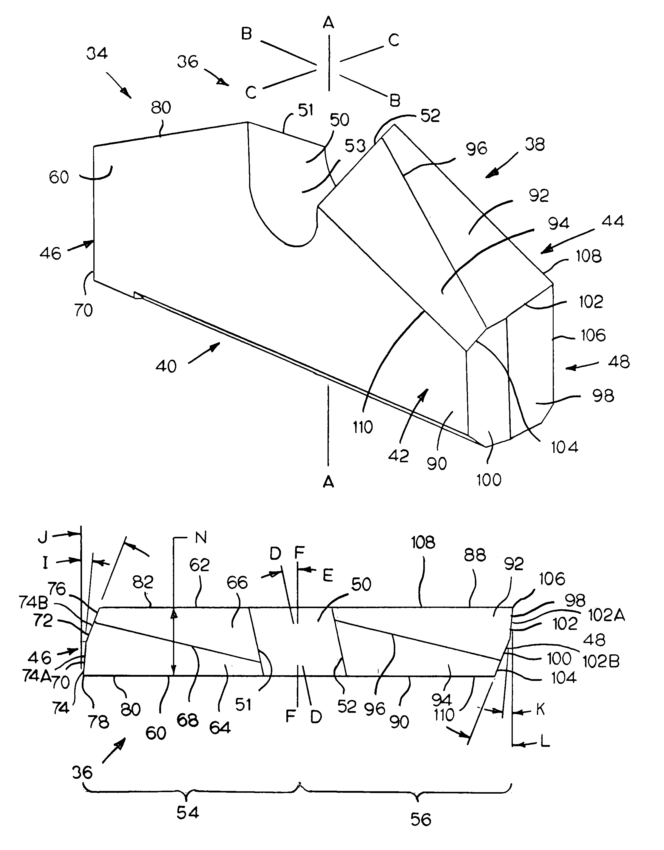
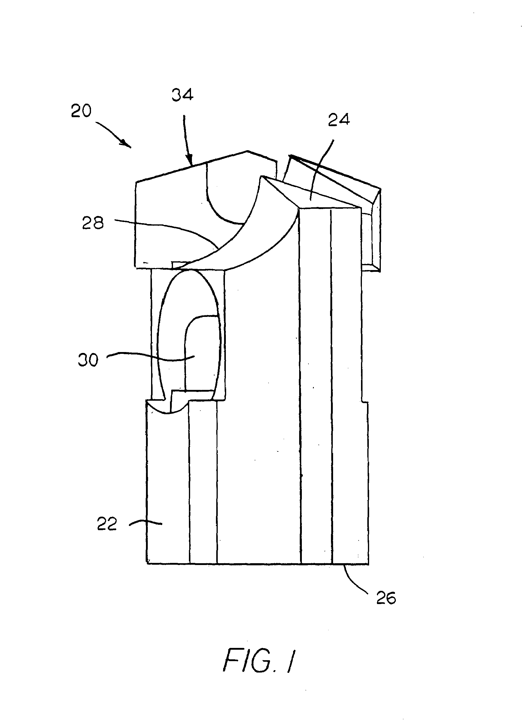
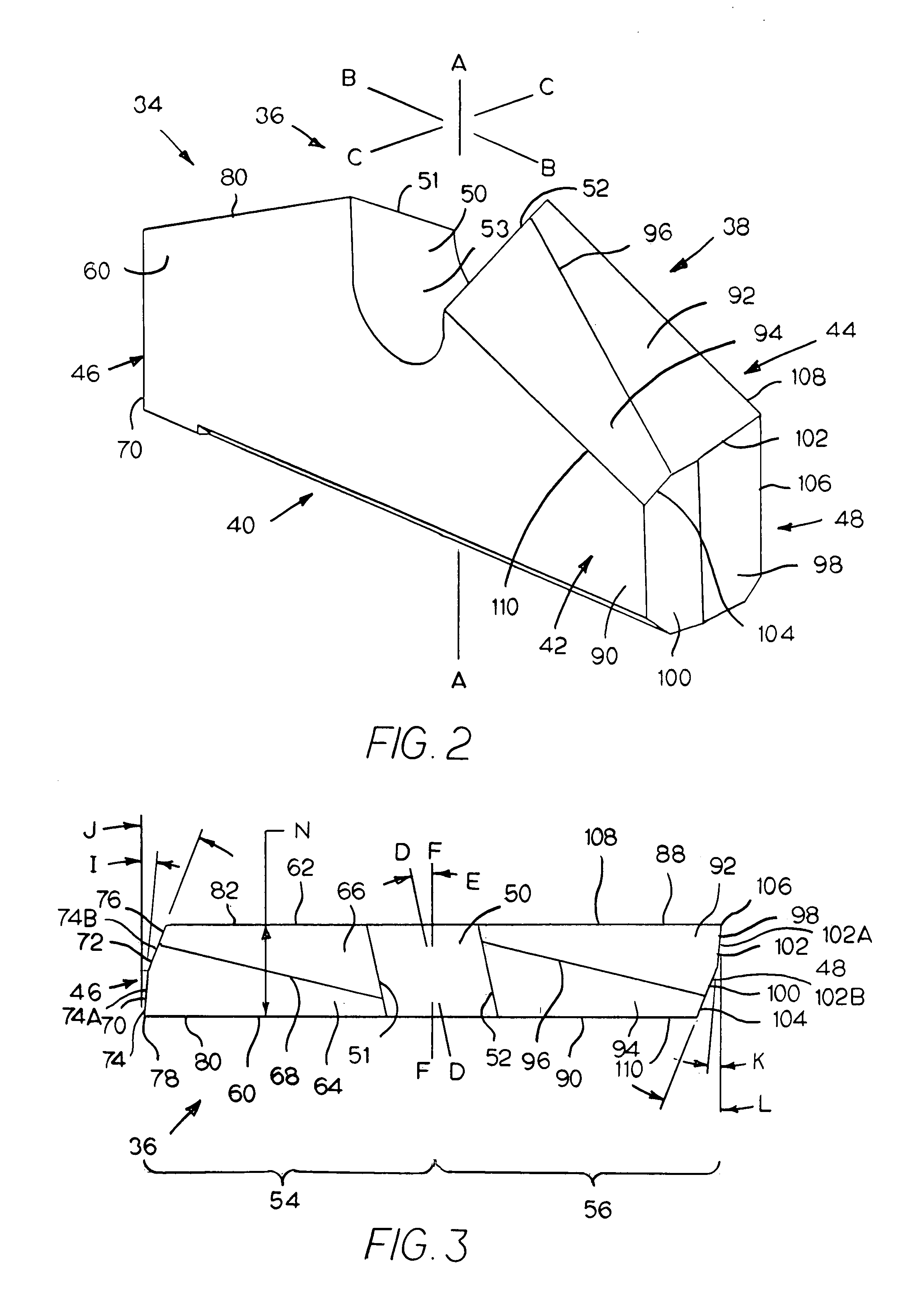
[0027]Referring to the drawings, FIG. 1 illustrates a rotary drill bit in the form of a roof drill bit generally designated as 20. Roof drill bit 20 has an elongate bit body 22 typically made of steel. Elongate bit body 22 presents a generally cylindrical geometry. Drill bit body 22 has an axial forward end 24 and an axial rearward end 26. Drill bit body 22 contains a transverse slot 28 in the axial forward end thereof 24. Drill bit body 22 also contains a dust collection opening 30 that is mediate between the axial forward end 24 and the axial rearward end 26. During the drilling operation, dirt and debris may pass through the opening 30. A cutting insert (or rotary drill bit insert) 34 is positioned within the transverse slot 28 and is typically affixed therein by brazing.

[0028]The cutting insert 34 is typically made from cemented tungsten carbide that is a mixture of cobalt and tungsten carbide. U.S. Pat. No. 5,467,837 to Miller et al. (assigned to the assignee of the present pat...


PUM


Abstract

A rotary drill bit insert that includes an elongate body that is rotatable about a central axis wherein the elongate body has a pair of symmetrical halves symmetrical about the central axis. The elongate body contains a central notch disposed between the symmetric halves of the elongate body. Each symmetrical half includes a leading face and a top surface that has a leading surface and a trailing relief surface wherein the leading surface and the trailing relief surface are contiguous and non-coplanar. Each half also has a leading cutting edge at the intersection of the leading face and the leading surface of the top surface. The leading surface is inclined at a constant angle of inclination in a radial direction with respect to a first radial line projecting from the central axis, and the leading surface being inclined downwardly and rearwardly from the leading cutting edge.

Description

BACKGROUND OF THE INVENTION[0001]The invention pertains to an excavating tool such as, for example, a rotary drill bit, including the cutting insert therefor, and a method of drilling using the rotary drill bit, wherein the bit is useful for drilling through various earth strata. More specifically, the invention pertains to a roof drill bit, including the cutting insert therefor, and a method for using the roof drill bit, wherein the bit is useful for drilling bore holes in an underground mine.[0002]The expansion of an underground mine, such as for example, a coal mine, requires digging a tunnel. Initially, this tunnel has an unsupported roof. Because the roof is not supported, there is an increased chance for a mine cave that, of course, adds to the hazards of underground coal mining. Furthermore, an unsupported roof is susceptible to rock and debris falling from the roof. Falling rock and debris can injure workers as well as create hazardous clutter on the floor of the tunnel.[000...

Claims


Application Information

Patent Timeline
Patent Type & Authority Patents(United States)
IPC IPC(8): E21B10/30E21B10/58
CPCE21B10/58
Inventor WOODS, GERALD L.ALCORN, LYNN A.
Owner KENNAMETAL INC
Learn More