Dishwasher rack assemblies

a technology for dishwashing racks and dishwashing machines, applied in the field of dishwashing racks, can solve the problem of limited vertical space in the washing chamber

Active Publication Date: 2007-01-30
HAIER US APPLIANCE SOLUTIONS INC
View PDF19 Cites 46 Cited by
  • Summary
  • Abstract
  • Description
  • Claims
  • Application Information

AI Technical Summary

Problems solved by technology

However, the washing chamber has limited available vertical space.

Method used


Image

  • Dishwasher rack assemblies
  • Dishwasher rack assemblies
  • Dishwasher rack assemblies

Examples


Embodiment Construction

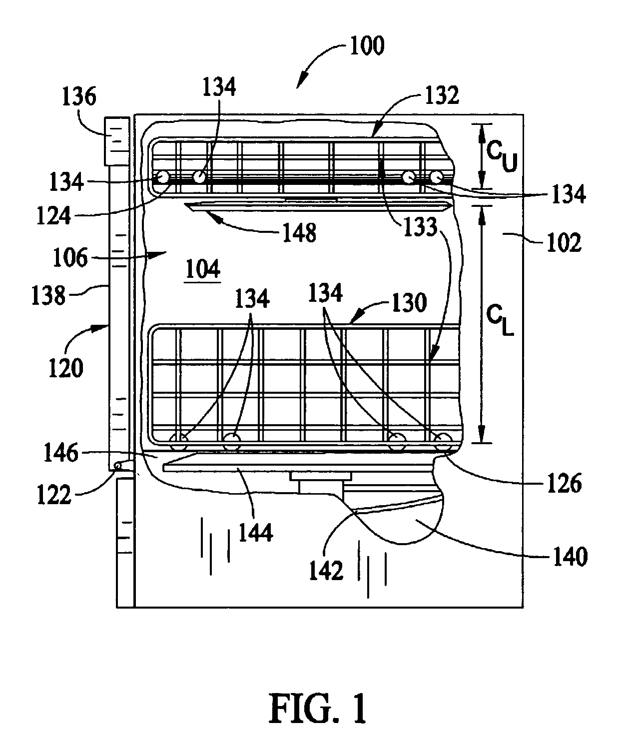
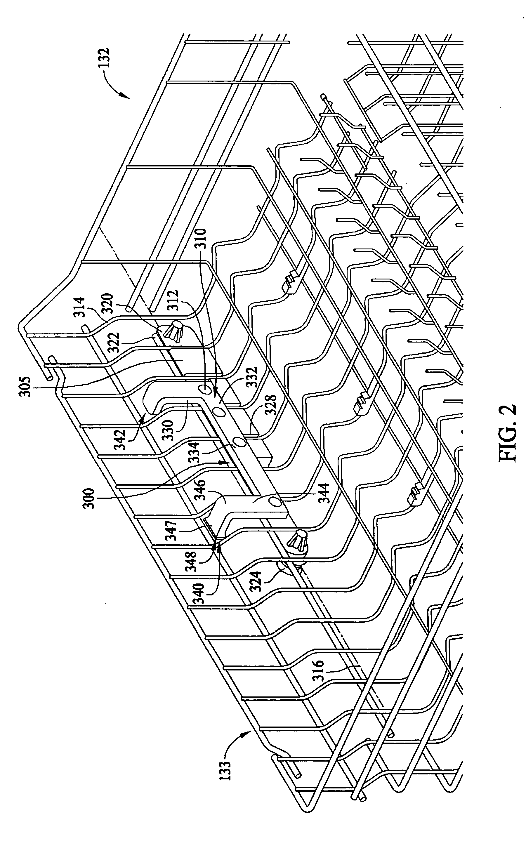
[0014]FIG. 1 is a side elevational view of an exemplary dishwasher 100. Dishwasher 100 includes a cabinet 102 having a tub 104 therein and forming a wash chamber 106. Tub 104 includes a front opening (not shown in FIG. 1) and a door assembly 120 hinged at its bottom 122 for movement about a horizontal axis between a normally closed vertical position (shown in FIG. 1) wherein wash chamber 106 is sealed shut for washing operation, and a horizontal open position (shown in FIG. 2) for loading and unloading of cookware from wash chamber 106. Upper and lower guide rails 124, 126 are mounted on side walls of tub 104 and accommodate a lower cookware rack 130 and an upper cookware rack 132 respectively. Each rack 130, 132 has at least one lateral side 133 that is adapted for horizontal movement on rollers 134 between an extended loading position (not shown) in which the rack is substantially positioned outside wash chamber 106, and a retracted position (shown in FIG. 1) in which the rack is ...


PUM


Abstract

An adjustable rack assembly configured to couple to a sidewall of a dishwasher rack is provided. The sidewall having at least one horizontal wire member and at least one vertical wire member. The adjustable rack assembly includes a bracket on one side of the sidewall, the bracket supporting the at least one horizontal wire member in a first rack position and a support plate on another side of the sidewall, the support plate coupled to the bracket, the support plate having at least one arm with a catch member on a distal end thereof for receiving the at least one horizontal wire member in a second rack position.

Description

BACKGROUND OF THE INVENTION[0001]This invention relates generally to dishwashers, and more particularly, to dishware racks disposed within dishwashers.[0002]At least some known dishwashers include a cabinet, a tub within the cabinet that defines an open sided wash chamber, and a door assembly that seals the open side of the wash chamber when the dishwasher is in use. Soiled dishes, glasses, utensils, food and beverage containers, etc. are loaded into the dishwasher tub through the open side of the wash chamber when the door is open, and after the door is closed, a dishwasher cycle may be executed to clean the items placed therein. The wash chamber includes a sump portion where washing fluid is pumped from a fluid circulation assembly through spray arm conduits to wash items loaded onto dishwasher racks in the wash chamber, and also where wash fluid is collected after being circulated throughout the wash chamber. The door assembly is attached to the dishwasher at a bottom end of the ...

Claims


Application Information

Patent Timeline
Patent Type & Authority Patents(United States)
IPC IPC(8): A47L15/50A47G19/08
CPCA47L15/504
Inventor MERSCH, MATTHEW DAVIDTOBBE, JOSEPH DUANEUTSCHIG, MICHAEL JOHNNOLAN, KEVIN FARRELLYMILLER, GREGORY OWEN
Owner HAIER US APPLIANCE SOLUTIONS INC
Why Eureka
Try Eureka