Ink-jet print head and ink-jet recording apparatus

a printing head and inkjet technology, applied in printing and other directions, can solve the problems of insufficient ink supply to the ink chamber, inability to print, and inability to meet the needs of ink supply, and achieve the effect of eliminating the shortage of ink supply

Inactive Publication Date: 2007-02-06
SII PRINTEK
View PDF3 Cites 7 Cited by
  • Summary
  • Abstract
  • Description
  • Claims
  • Application Information

AI Technical Summary

Benefits of technology

[0017]In view of the foregoing, it is an object of the invention to provide an ink-jet print head and ink-jet recording apparatus which are adapted to prevent the dwell of the air bubbles contained in the ink and to purge the air bubbles relatively easily.
[0033]According to the invention, at least one of the tapered portion opened progressively wider toward the ink chamber and the throttling portion narrowing the flow path toward the ink chamber is provided in the ink reservoir whereby the air bubbles contained in the ink are prevented from remaining in the ink reservoir so as to eliminate the shortage of ink supply. Furthermore, the invention permits the air bubbles to be relatively easily removed from the nozzle apertures.

Problems solved by technology

Such an ink-jet print head has a problem of ink jet failure which, for example, is caused by foreign substances contained in the ink.
Unfortunately, the ink reservoir of the conventional ink-jet print head includes a region where the ink flow tends to stagnate.
The accumulation of the air bubbles in such a region reduces the ink volume in the ink reservoir so that a shortage of ink supply to the ink chamber results.
Particularly when the ink, such as an aqueous ink, which is prone to form bubbles of low penetration is used, the dwell of the air bubbles is pronounced.
Unfortunately, the cleaning operation cannot fully remove the air bubbles from the region where the ink flow stagnates.
Thus, the ink-jet print head incapable of removing the air bubbles from the region suffering the ink flow stagnation is discarded because the remaining air bubbles are allowed to pass the filter during printing operations to be ejected along with the ink droplets so that a print failure results.
As a result, the yield is decreased.
Accordingly, the shortage of ink supply to the ink chamber becomes more and more serious.
However, the size of the filter is substantially decreased, resulting in the shortage of ink supply to the common ink chamber.

Method used


Image

  • Ink-jet print head and ink-jet recording apparatus
  • Ink-jet print head and ink-jet recording apparatus
  • Ink-jet print head and ink-jet recording apparatus

Examples


first embodiment

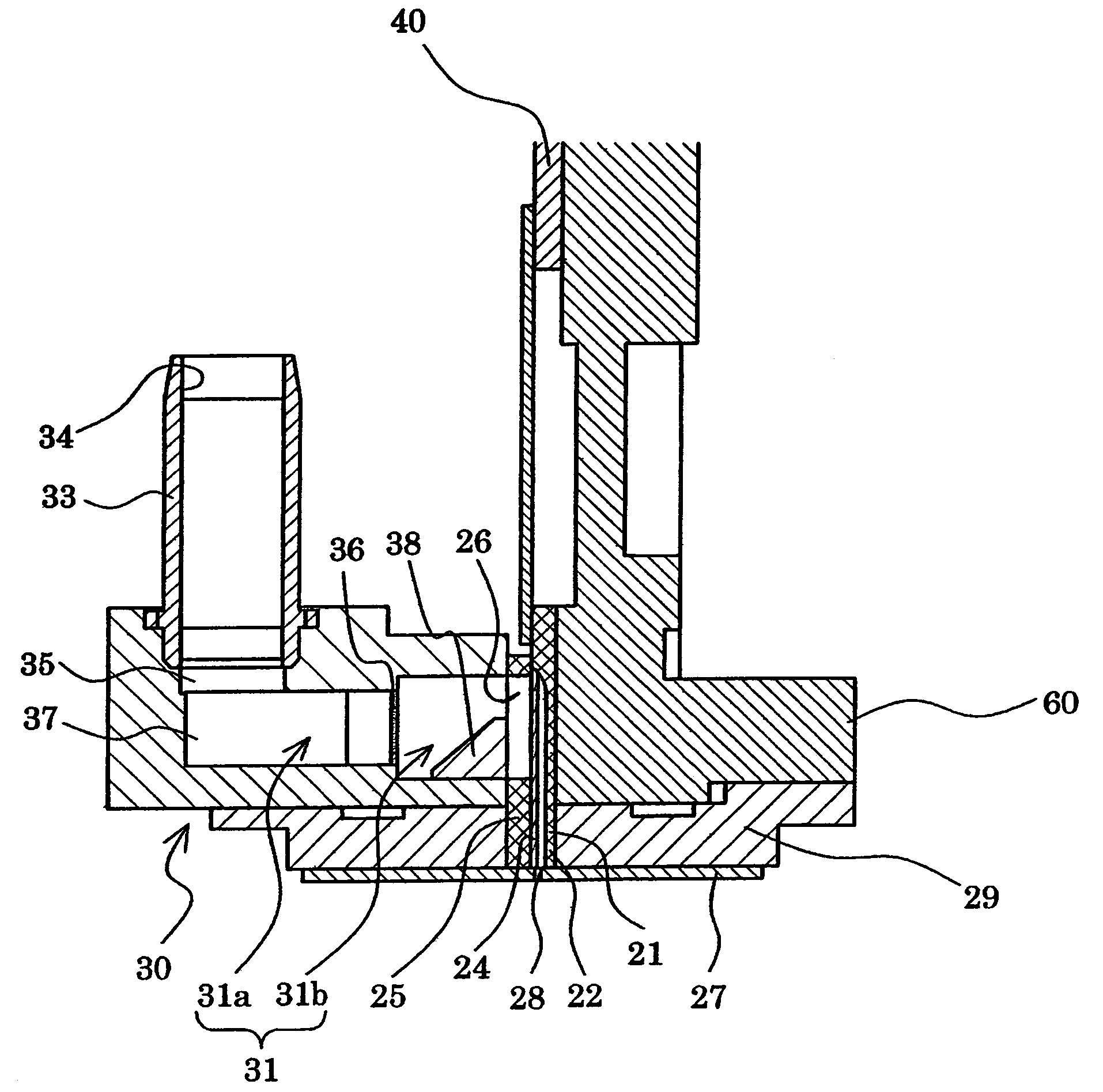
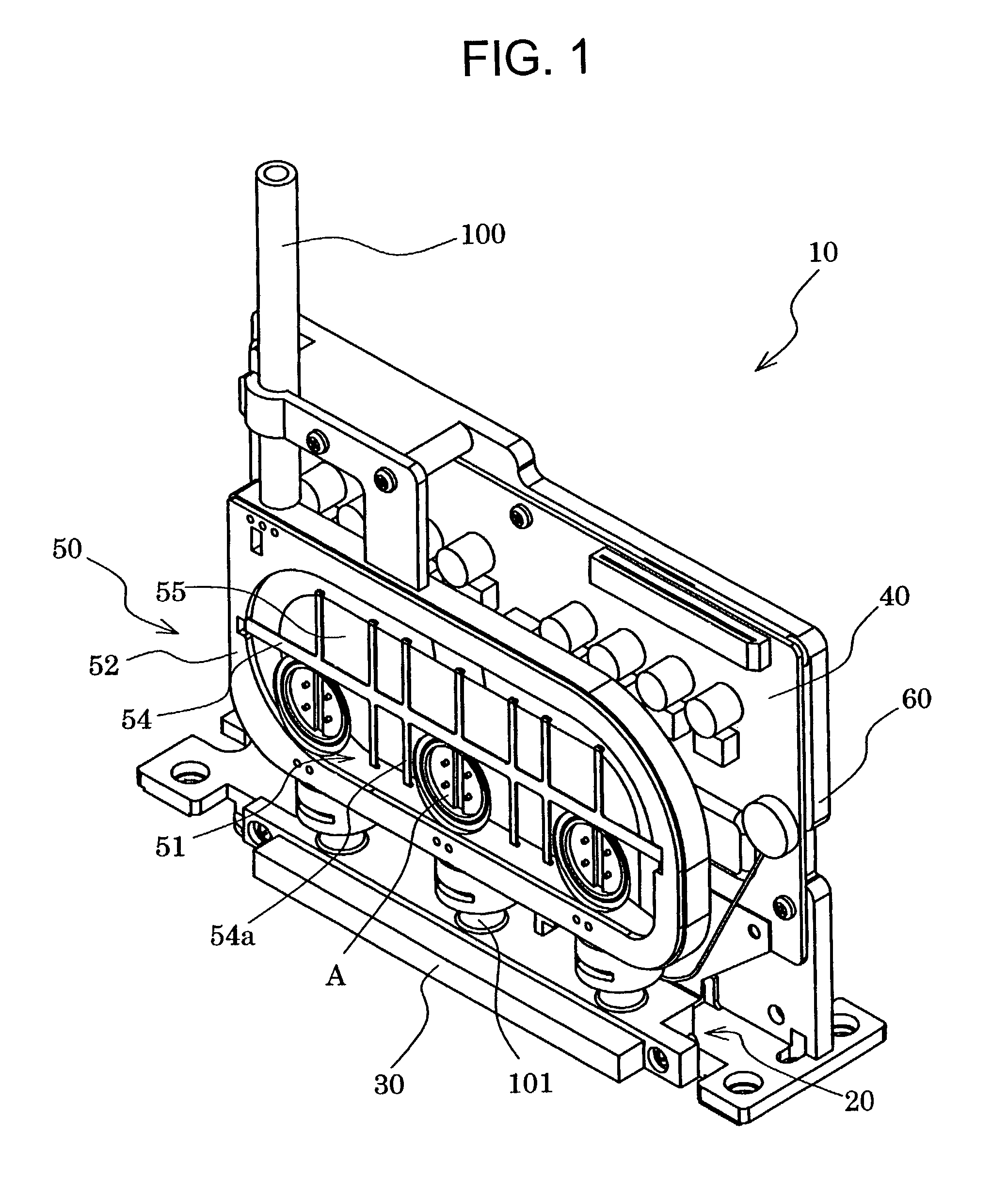
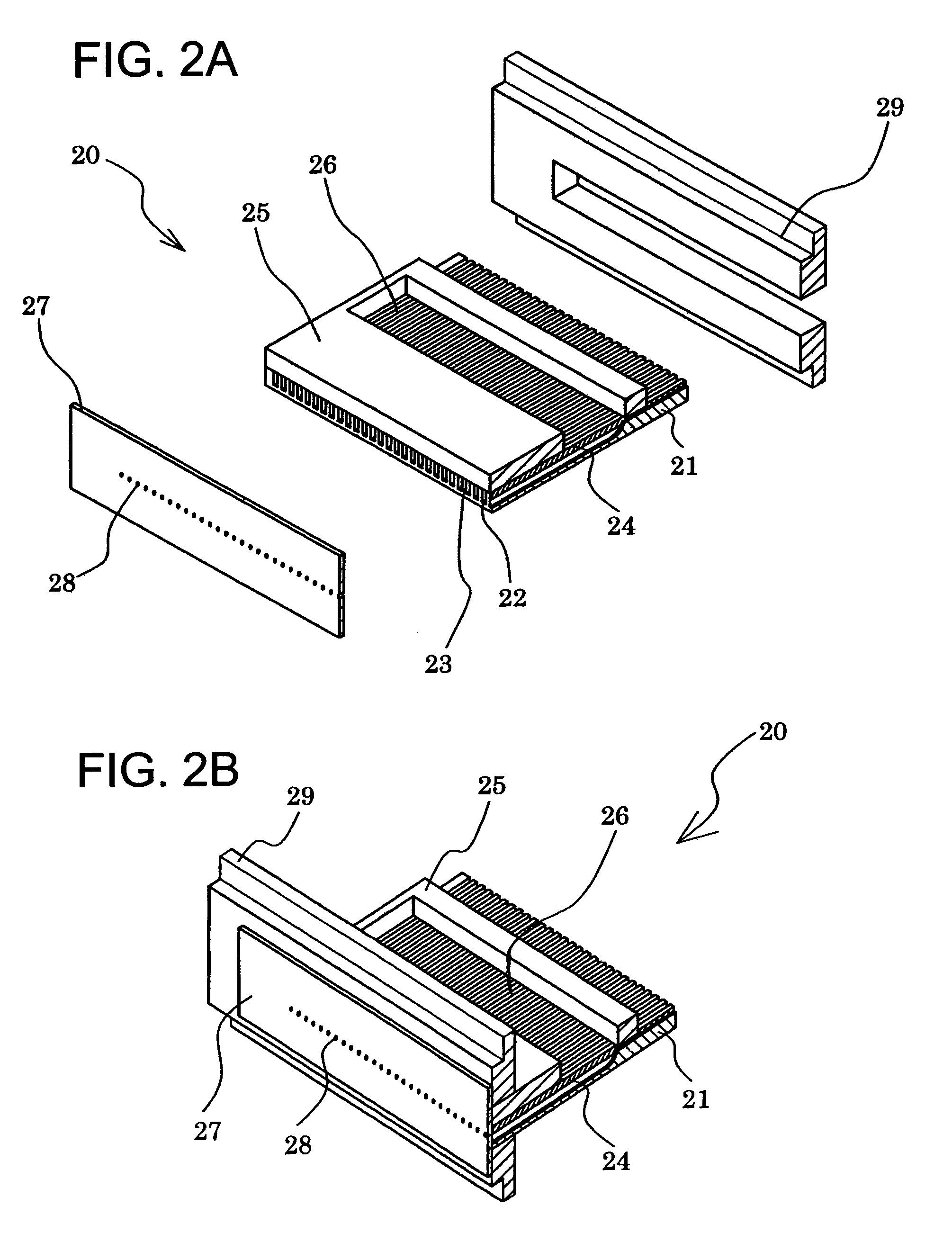
[0050]FIG. 1 is a perspective view showing an ink-jet print head according to a first embodiment. FIGS. 2A–2B are an exploded perspective view and a perspective sectional view, respectively, showing a head chip. FIG. 3 is a sectional view showing a principal part of the ink-jet print head.

[0051]As shown in the figures, an ink-jet print head 10 according to the embodiment includes a head chip 20, a flow-path base plate 30 disposed on one side of the head chip, a wiring board 40 having a drive circuit for driving the head chip 20 and others mounted thereon, and an air damper 50 for reducing pressure variations in the head chip 20, these components being secured to a base plate 60.

[0052]A piezoelectric ceramic plate 21 constituting the head chip 20 is formed with a plurality of grooves 22 extended in parallel relation and communicated with nozzle apertures. The individual grooves 22 are separated from one another by side walls 23. Each of the grooves 22 has one longitudinal end thereof...

second embodiment

[0097]FIG. 8 is a group of schematic diagrams showing a flow-path base plate according to a second embodiment of the invention, with FIG. 8A representing a perspective view thereof, FIG. 8B representing a plan view thereof and FIG. 8C representing a sectional view taken on the line B–B′ in FIG. 8B.

[0098]As shown in the figures, a flow-path base plate 30A according to the embodiment comprises a flow path body 32A having an ink reservoir 31A, a sealing base plate 70 for sealing the ink reservoir 31A of the flow path body 32A, and a communication portion 33A joined to the sealing base plate 70 substantially at a central portion thereof and having an ink supply path 34A for supplying the ink to the ink reservoir 31A.

[0099]The flow path body 32A is provided with a communication hole 35A of a great width which is extended between longitudinally opposite ends of the flow path body and communicated with the ink reservoir.

[0100]The sealing base plate 70 includes a through hole 71 communicate...


PUM


Abstract

An ink-jet print head has a piezoelectric ceramic plate having grooves for receiving ink, a nozzle plate connected to the piezoelectric ceramic plate and having nozzle apertures each disposed in communication with respective ones of the grooves, and an ink storing device for storing ink. An ink chamber plate is connected to the piezoelectric ceramic plate and has an ink chamber for supplying ink from the ink storing device to the grooves. A base plate is connected to a side of the ink chamber plate and has an ink reservoir defining a portion of an ink flow path for transporting ink from the ink storing device to the ink chamber of the ink chamber plate. The ink reservoir has at least one tapered portion progressively diverging in a direction toward the ink chamber of the ink chamber plate.

Description

BACKGROUND OF THE INVENTION[0001]1. Field of the Invention[0002]The present invention relates to an ink-jet print head and an ink-jet recording apparatus adapted for printing by ejecting an ink droplet from a nozzle aperture, and more particularly, to an ink-jet print head and ink-jet recording apparatus which employ an ink, such as an aqueous ink, which is prone to form bubbles hard to penetrate.[0003]2. Description of the Related Art[0004]Conventionally, ink-jet recording apparatuses have been known which are adapted to record characters or images on a receiving medium by means of an ink-jet print head having a plurality of nozzles for ink ejection. In such ink-jet recording apparatuses, the ink-jet print head is assembled with a head holder as directing its nozzles toward the receiving medium, whereas the head holder is mounted to a carriage to scan along a direction orthogonal to a direction in which the receiving medium is conveyed.[0005]One example of such an ink-jet print hea...

Claims


Application Information

Patent Timeline
Patent Type & Authority Patents(United States)
IPC IPC(8): B41J2/045B41J2/14B41J2/175
CPCB41J2/14145
Inventor TOMINAGA, KAZUYOSHIKOSEKI, OSAMUDENDA, MASAKIMAKISHIMA, TOMIHARUSEKIYA, YASUHITOTSUNEYOSHI, JUNNAKAMURA, YUUJISUZUKI, KENTAROU
Owner SII PRINTEK
Why Eureka
Try Eureka