
Apparatus for adjusting a signal based on a position of a movable member

a technology of a moving member and an apparatus, which is applied in the direction of electrical transducers, gain control, instruments, etc., can solve the problems of contact tending to be worn down

Inactive Publication Date: 2007-02-27
PIONEER DJ
View PDF19 Cites 3 Cited by
  • Summary
  • Abstract
  • Description
  • Claims
  • Application Information

AI Technical Summary

Benefits of technology

The solution enables secure and precise adjustment of audio signals, reducing detection errors and maintaining performance over time, while also simplifying component selection and reducing production costs.

Problems solved by technology

The conventional signal adjusting apparatus described above, however, encounters such a problem that the slide volume cannot securely adjust the audio signal, resulting from the fact that the slide volume is a contact type of detector with an electrical and mechanical contact tending to be worn down under the state that the operation lever is repeatedly moved by an operator.

Method used


Image

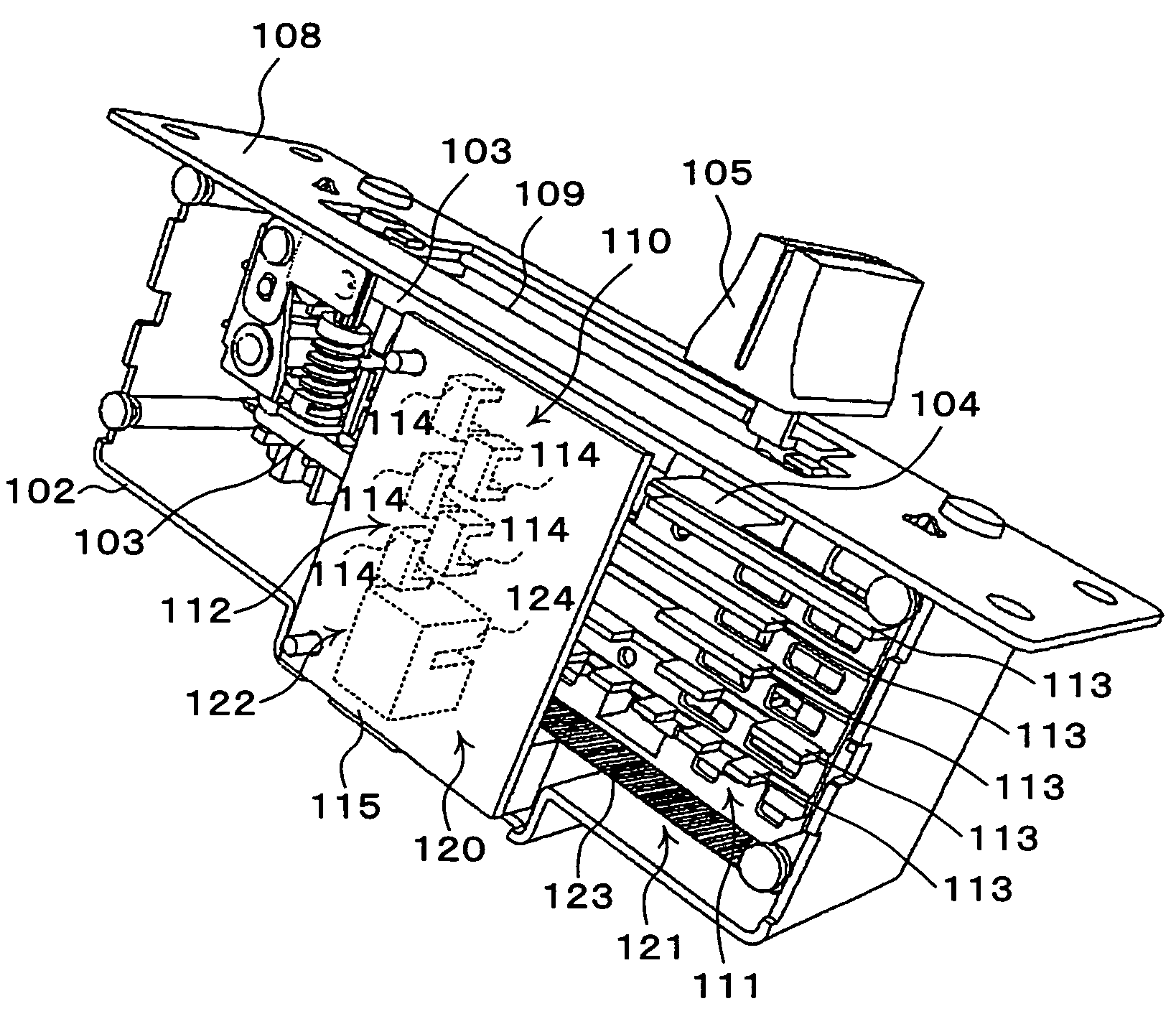
  • Apparatus for adjusting a signal based on a position of a movable member
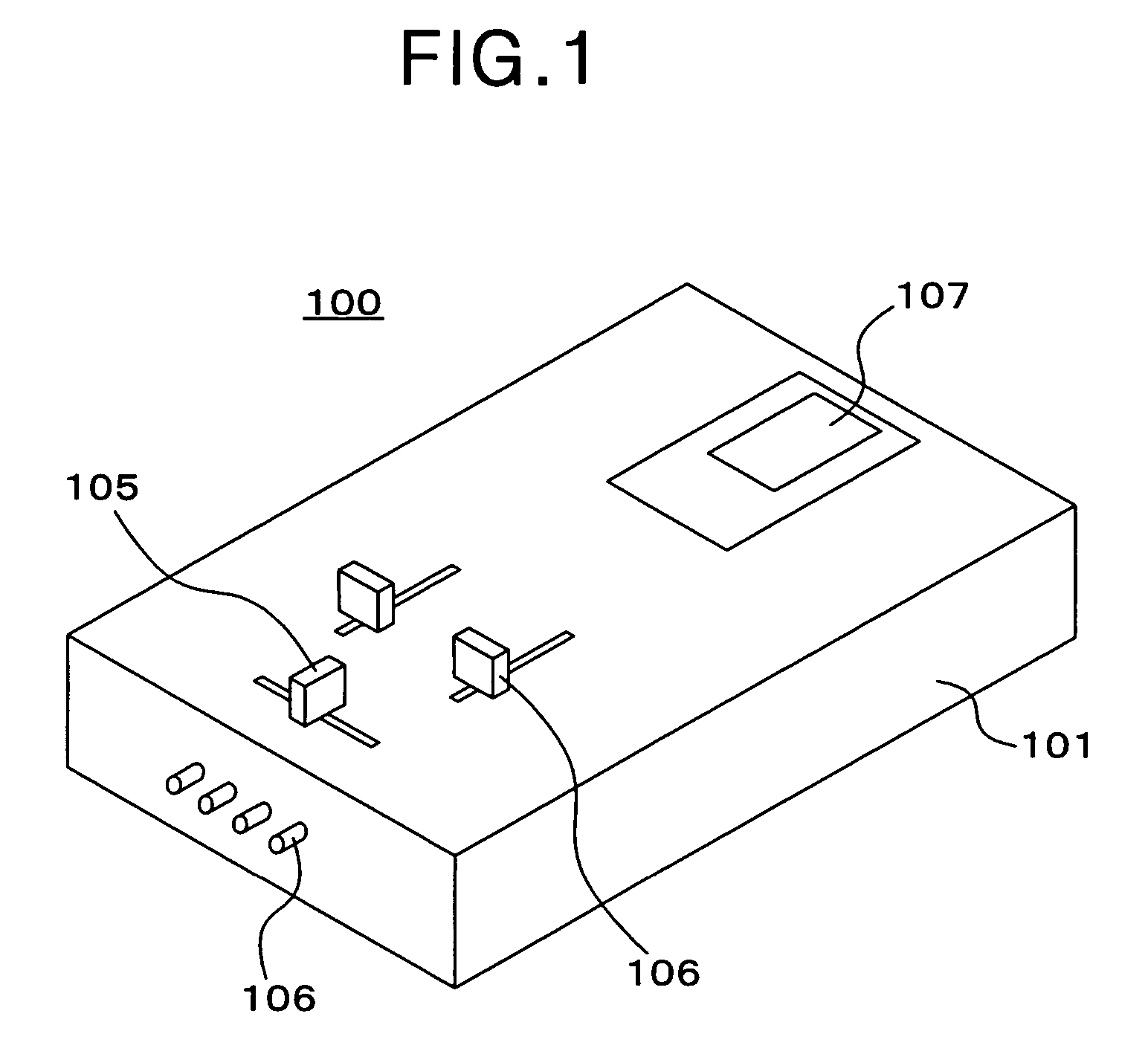
  • Apparatus for adjusting a signal based on a position of a movable member
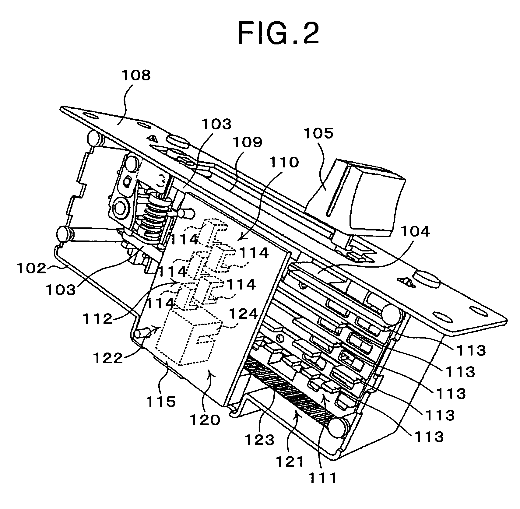
  • Apparatus for adjusting a signal based on a position of a movable member

Examples


Embodiment Construction

[0022]One preferred embodiment of the signal adjusting apparatus according to the present invention will now be described in detail in accordance with the accompanying drawings.

[0023]Referring now to the drawings, in particular to FIGS. 1 to 12, there is shown one preferred embodiment of the signal adjusting apparatus according to the present invention.

[0024]The construction of the signal adjusting apparatus in this embodiment will be described hereinafter.

[0025]The signal adjusting apparatus in this embodiment is applied to an audio mixer which is operative to adjust an audio signal.

[0026]In this embodiment, while the signal adjusting apparatus according to the present invention is applied to an audio mixer used for a variety of audio instruments, the signal adjusting apparatus according to the present invention may be applied to a controller used for a variety of robot instruments, a controller used for a variety of game machines, an interface used for a variety of electric musica...


PUM


Abstract

A signal adjusting apparatus comprises a movable member, a first detecting device, a second detecting device, and a correction device. The member is movable in a movable range composed of a plurality of intervals. The first detecting device detects one of the intervals where the member is located. The first detecting device is constituted by a first movable portion mounted on the member and a first fixed portion spaced apart from the first movable portion. The one of the intervals is an absolute position. The second detecting device detects a relative position of the member within the detected interval. The second detecting device is constituted by a second movable portion mounted on the member and a second fixed portion spaced apart from the second movable portion. The correction device corrects the detected relative position based on a relationship between the absolute position and the relative position stored in a memory.

Description

BACKGROUND OF THE INVENTION[0001]1. Field of the Invention[0002]The present invention relates to a signal adjusting apparatus, and more particularly to a signal adjusting apparatus which is operative to adjust an electrical signal.[0003]2. Description of the Related Art[0004]Up to now, there have been proposed a variety of conventional signal adjusting apparatuses each of which is operative to adjust an electrical signal. One typical example of the conventional signal adjusting apparatuses is adapted to an audio mixer which is operative to adjust an audio signal. This type of signal adjusting apparatus is disclosed in U.S. Pat. No. 6,301,365.[0005]The conventional signal adjusting apparatus thus proposed comprises an operation lever which is movably supported, and a slide volume which detects a position of the operation lever and adjusts the audio signal based on an adjustment state corresponding to the position of the operation lever. The adjustment state is, for example, previousl...

Claims


Application Information

Patent Timeline
Patent Type & Authority Patents(United States)
IPC IPC(8): G01D5/34H04R3/00G01D5/347
CPCG01D5/34792
Inventor MINOKAMI, JUNKATAOKA, YOSHINORIKAKUTA, YOSHIYUKIOGA, CHIHAYAFUNADA, TAKEAKIYAMADA, YOUICHIKASUYA, SATOMISHIRAISHI, TATSUYA
Owner PIONEER DJ
Learn More