Motion compensator

a technology of motion compensation and compensator, which is applied in the direction of sealing/packing, drilling pipes, and well accessories, etc., can solve the problems of large volume, damage or breakage of conventional devices used to accommodate such movements, and excessive force to be experienced on equipmen

Active Publication Date: 2007-03-20
DEVIN INT
View PDF10 Cites 23 Cited by
  • Summary
  • Abstract
  • Description
  • Claims
  • Application Information

AI Technical Summary

Problems solved by technology

When servicing a subsea well from a floating vessel, tidal variations cause the vessel, as well as surface wellhead assemblies connected an upper end of a riser from the subsea well location, to drift.
The tidal drift can cause excessive forces to be experienced on the equipment that can damage or break the servicing equipment and the surface wellhead assembly.
Conventional devices used for accommodating for such movements are large and bulky in size.
These devices are so large that they cannot be used within a drilling rig.
Moreover, the conventional devices are not responsive to the tidal drift.
This process can be costly and dangerous, because it is desirous to keep the line supporting the servicing equipment taught so that as little weight as possible is supported by the surface wellhead assembly.

Method used


Image

  • Motion compensator
  • Motion compensator
  • Motion compensator

Examples


Embodiment Construction

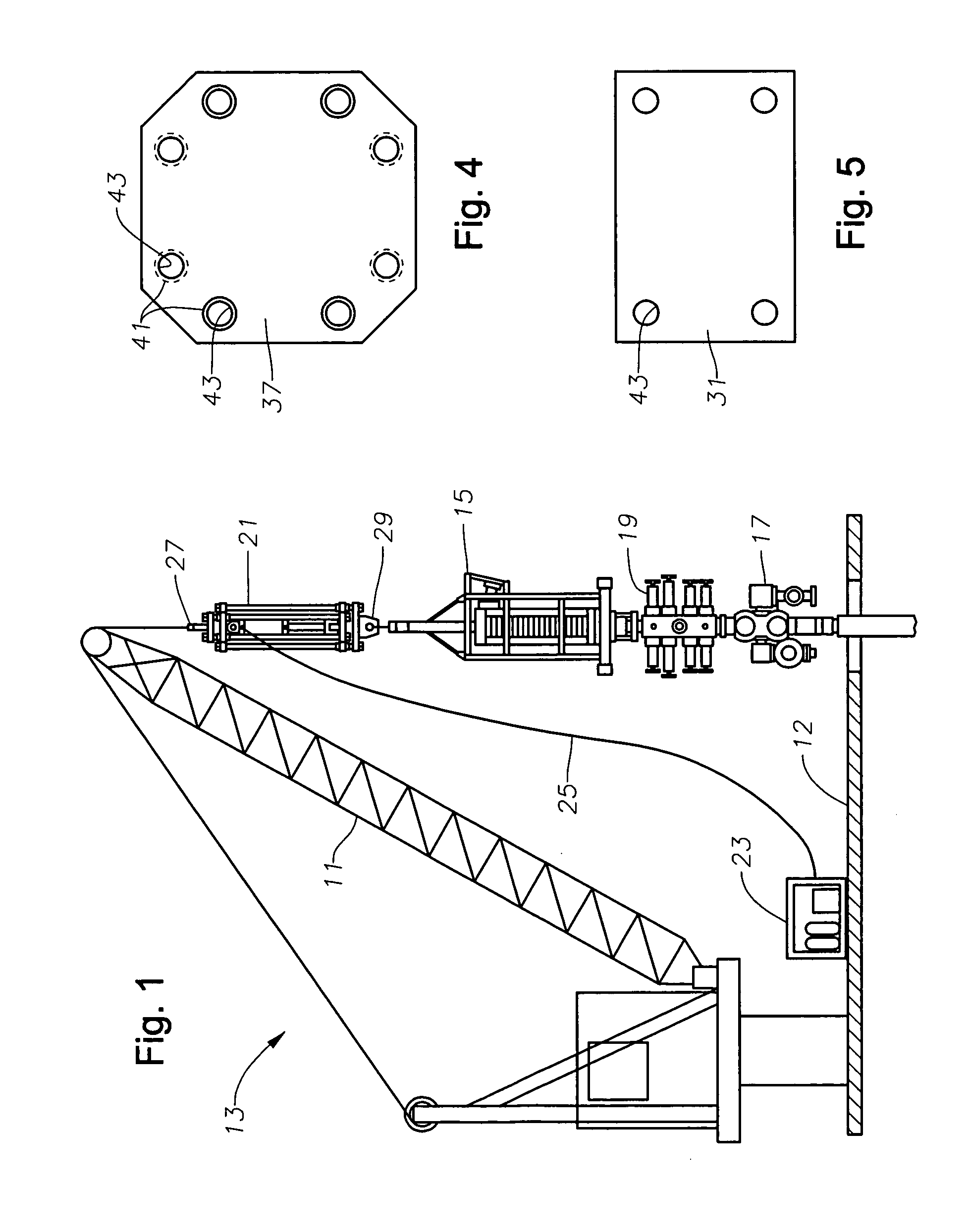
[0016]Referring to FIG. 1, a crane 11 is shown on top of a platform 13. Platform 13 is typically a platform associated with an offshore facility for oil wells. A surface wellhead assembly 17 rests atop of a distal end of casing that extends through a deck 12 of the platform to a subsea well (not shown) positioned below platform 13. A coiled tubing injector 15 is suspended from crane 11 for connection with wellhead 17. Coiled tubing injector 15 can be used in a manner known in the art for injecting coiled tubing in order to perform intervention on the well. A coiled tubing blowout preventer system 19 is preferably located between coiled tubing injector 15 and wellhead 17 in order to control possible blowouts from a well during operations.

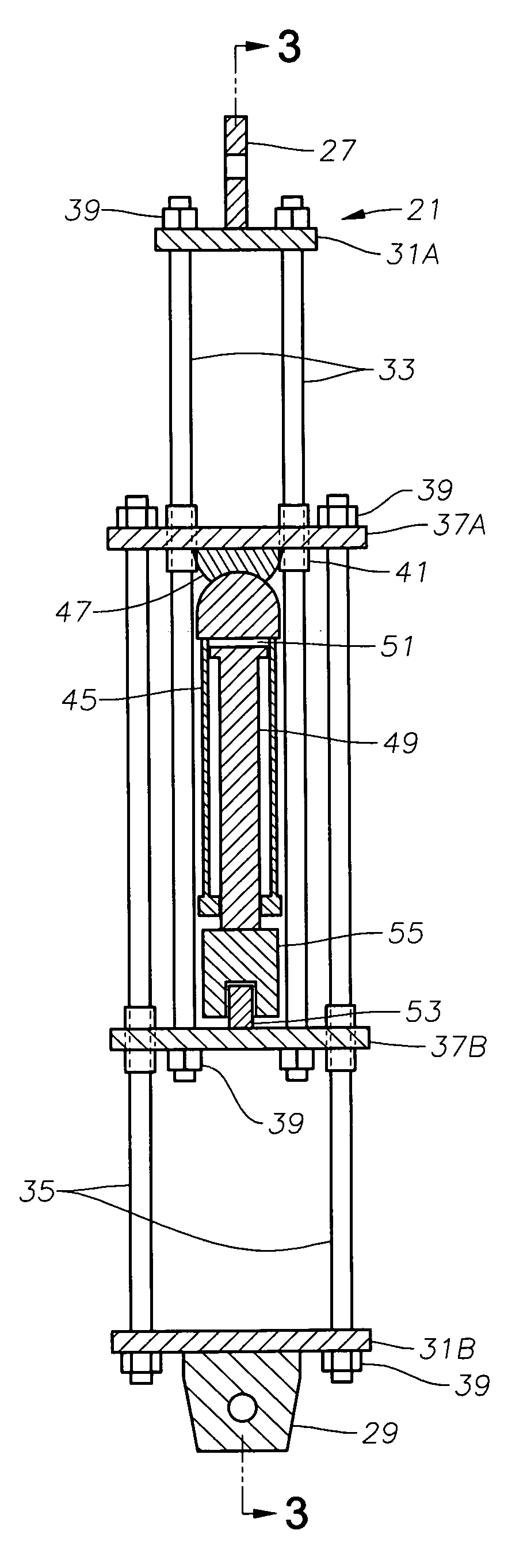
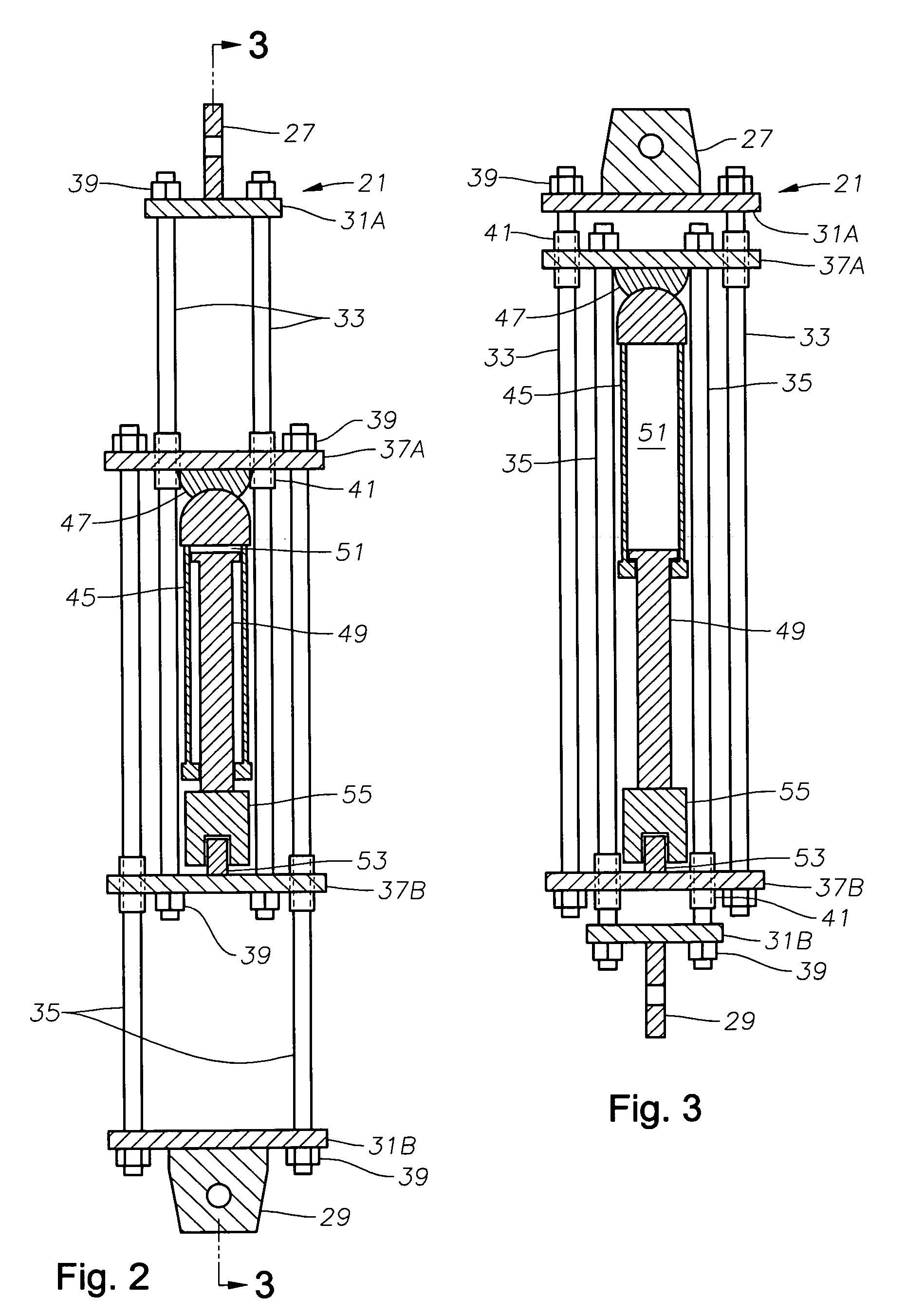
[0017]A motion compensator 21 is also suspended from crane 11 in a position above coiled tubing injector 15. Motion compensator 21 advantageously compensates for motions of platform 13 relative to wellhead 17 due to tidal variations of the water belo...


PUM


Abstract

A motion compensator is used on a floating vessel servicing a subsea well. The motion compensator includes a first frame assembly adapted to be connected to a cable extending from a lifting structure. When connected to the cable, the first frame assembly extends longitudinally along an axis substantially parallel with that of the cable. The motion compensator also includes a second frame assembly connected to the first frame assembly. The second frame assembly overlaps a longitudinal portion of the first frame assembly. The first and second frame assemblies are moveable relative to each other and define an expanded position and a contracted position. The motion compensator further includes a piston assembly positioned between the first and second frame assemblies. The piston assembly has a piston chamber and a piston that slidingly engages the piston chamber when the first and second rod assemblies move relative to each other.

Description

RELATED APPLICATIONS[0001]Applicant claims priority to the application described herein through a U.S. provisional patent application titled “Motion Compensator,” having U.S. Patent Application Ser. No. 60 / 589,300, which was filed on Jul. 20, 2004, and which is incorporated herein by reference in its entirety.BACKGROUND OF INVENTION[0002]1. Field of the Invention[0003]The present invention relates generally to offshore platforms, and more specifically to an assembly for compensating for motion.[0004]2. Background of the Invention[0005]When servicing a subsea well from a floating vessel, tidal variations cause the vessel, as well as surface wellhead assemblies connected an upper end of a riser from the subsea well location, to drift. This phenomenon is commonly known as “tidal drift.” When servicing the well through the surface wellhead assembly, the servicing equipment is typically suspended above the surface wellhead assembly. The typical servicing equipment can be the equipment co...

Claims


Application Information

Patent Timeline
Patent Type & Authority Patents(United States)
IPC IPC(8): E21B7/12
CPCE21B19/09
Inventor COLES, ROBERT A.
Owner DEVIN INT
Why Eureka
Try Eureka