Tool joint

a tool and joint technology, applied in the field of tools, can solve the problems of short bits not being used, few problems encountered in the use of this conventional screwdriver,

Inactive Publication Date: 2007-03-27
SHU ZU SHUNG
View PDF17 Cites 35 Cited by
  • Summary
  • Abstract
  • Description
  • Claims
  • Application Information

AI Technical Summary

Problems solved by technology

However, a few problems are encountered in use of this conventional screwdriver.
Firstly, short bits cannot be used, because the locking device 2 is located deep into the handle 1.

Method used


Image

  • Tool joint
  • Tool joint
  • Tool joint

Examples


Embodiment Construction

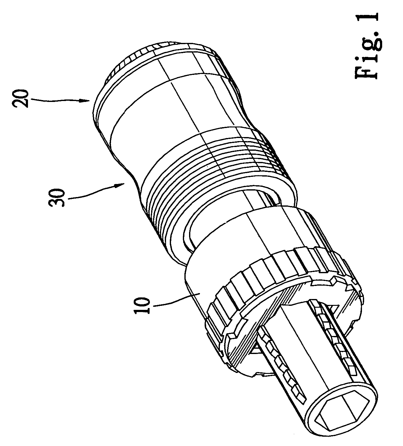
[0025]Referring to FIG. 1, according to a first embodiment of the present invention, a joint is shown to include a core 10, a locking device 30 and a locking device 20.

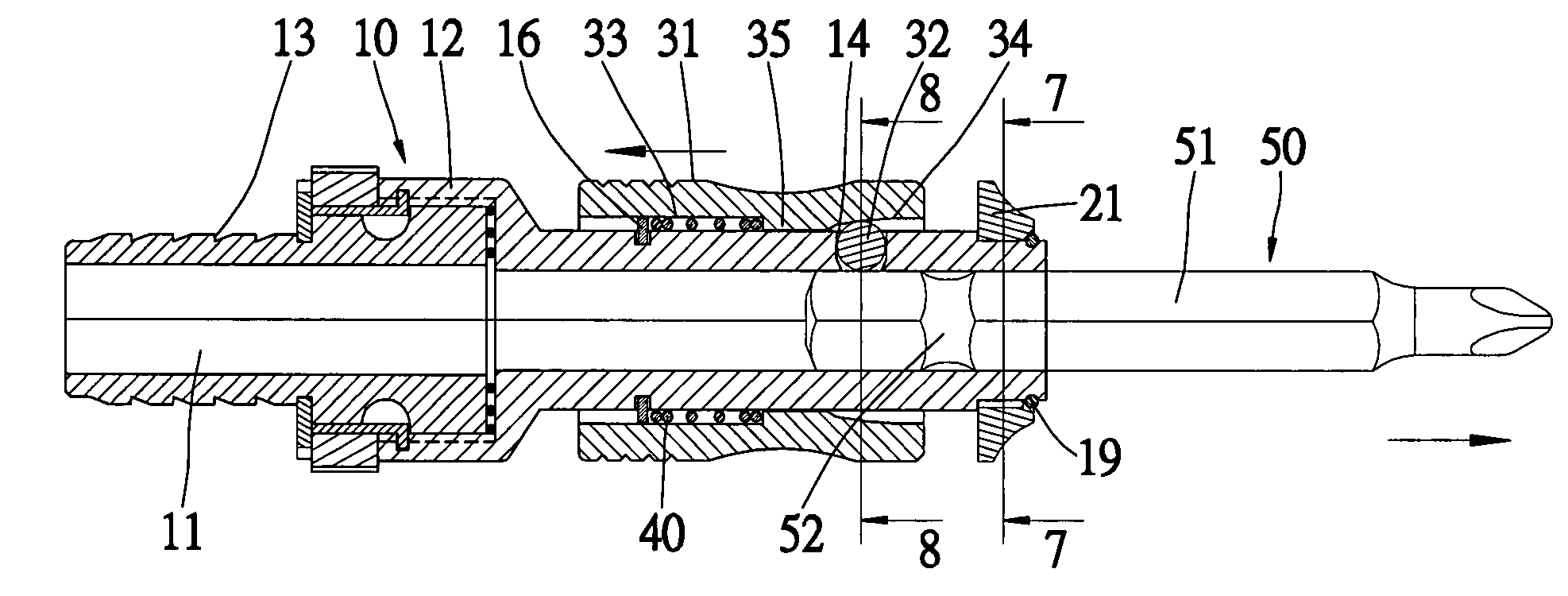
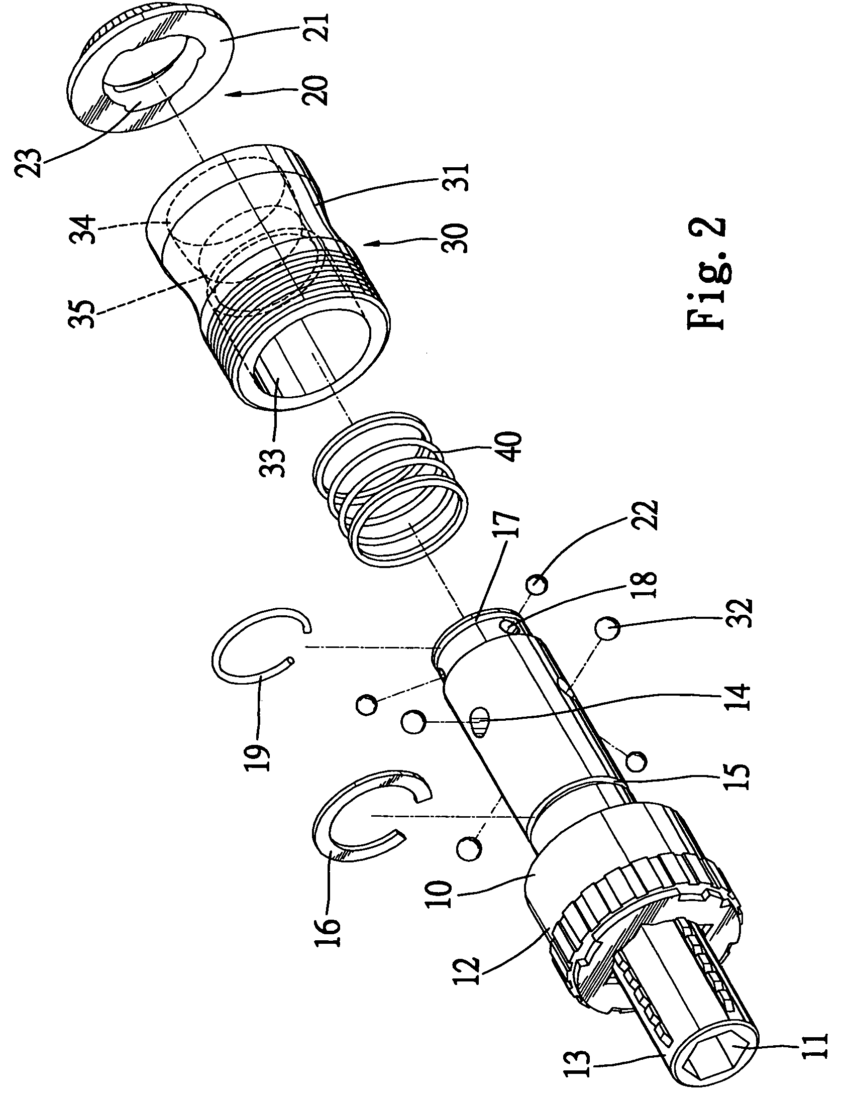
[0026]Referring to FIG. 2, the core 10 includes an insert 13 to be inserted in a handle (not shown) and a selective one-way socket 12 connected with the insert 13. An axial passage 11 extends through the insert 13 and the selective one-way socket 12.

[0027]The selective one-way socket 12 includes an annular groove 15 defined in the periphery, three apertures 14 communicated with the axial passage 11, three apertures 18 communicated with the axial passage 11 and an annular groove 17 defined in the periphery.

[0028]The locking device 30 includes three balls 32 put in the apertures 14 and a collar 31 for controlling the balls 32.

[0029]The locking device 20 includes three balls 22 put in the apertures 18 and a ring 21 for controlling the balls 22.

[0030]Referring to FIG. 3, the collar 31 includes an internal side that is div...


PUM

PropertyMeasurementUnit
rotationaaaaaaaaaa
elasticaaaaaaaaaa
areaaaaaaaaaaa

Abstract

A joint is disclosed for connecting a handle with various bits. The joint includes an insert fit in the handle, a socket connected with the insert for receiving the bits, a first locking device installed on the socket for locking long bits to the socket and a second locking device installed on the socket for locking short bits to the socket.

Description

BACKGROUND OF INVENTION[0001]1. Field of Invention[0002]The present invention relates to a tool and, more particularly, to a tool joint for connecting a handle with various bits.[0003]2. Related Prior Art[0004]In Taiwanese Patent M2403 11, a conventional screwdriver is disclosed. This conventional screwdriver includes a handle 1, a bit 3 inserted in the handle 1, a locking device 2 installed in the handle 1 in order to lock the bit 3 and a controlling device 4 installed on the handle 1 in order to control the locking device 2. The locking device 2 includes a socket 22 with an axial passage 221 for receiving the bit 3 and two apertures communicated with the axial passage 221. An annular flange is formed on the socket 22. Two balls 222 are put in the apertures of the socket 22. A ring 21 is installed on the socket 22. The ring includes a tapered internal side 211 for pushing the balls 222. A spring 24 is installed on the socket 22. A C-clip is engaged with the socket 22 opposite to th...

Claims


Application Information

Patent Timeline
Patent Type & Authority Patents(United States)
IPC IPC(8): B23Q5/22
CPCB25B23/0035Y10T408/953Y10T279/17752Y10T279/17145Y10T279/17803
Inventor SHU, ZU-SHUNG
Owner SHU ZU SHUNG
Why Eureka
Try Eureka