Sub-miniature switch

a sub-miniature switch and switch technology, applied in the direction of snap-action arrangements, contact mechanisms, electrical devices, etc., can solve the problems of destroying the drive, affecting the manufacture and assembly of these micro-switches, and affecting the operation of the switch

Inactive Publication Date: 2007-04-17
ZF FRIEDRICHSHAFEN AG
View PDF10 Cites 21 Cited by
  • Summary
  • Abstract
  • Description
  • Claims
  • Application Information

AI Technical Summary

Benefits of technology

[0008]This approach is simpler than the known solutions of the prior art and enables a forced opening to be effected at this contact point in the case of a fusion of the so-called NC contact, wherein the separator directly contacts the contact maker and causes the fused contacts to tear open by the application of a force which is parallel to the direction of movement.

Problems solved by technology

The capacitive loads on the contacts in the end-of-travel positions easily lead to sticking or fusing of the contacts.
This can lead to the destruction of the drive as it is not switched off.
Due to the addition of a component, the manufacture and assembly of these micro-switches is made more complex.

Method used


Image

  • Sub-miniature switch
  • Sub-miniature switch
  • Sub-miniature switch

Examples


Embodiment Construction

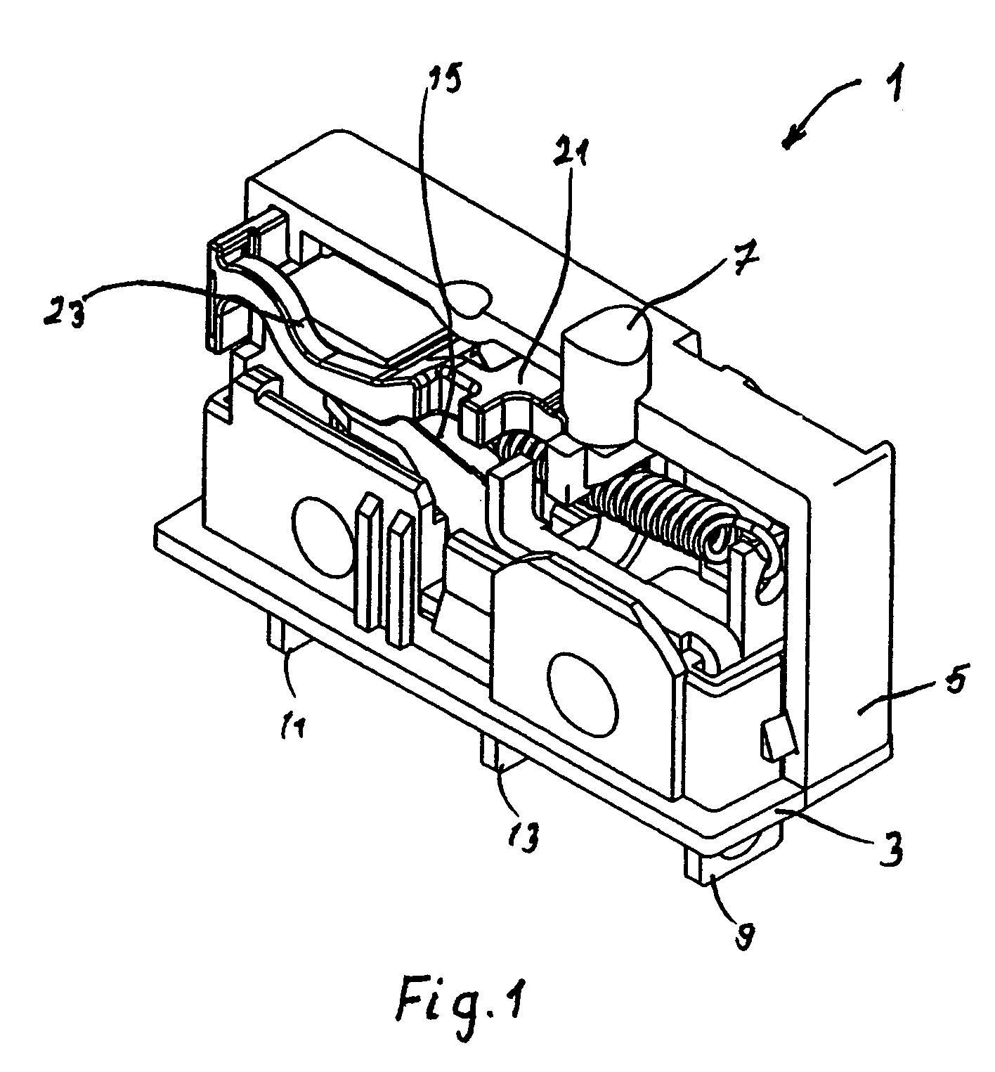
[0014]In the perspective view according to FIG. 1, the sub-miniature switch 1 can be seen with the actuator 7 at the top and the contact tabs or terminals 9, 11 and 13 at the bottom. The structure is supported on the base 3 of the housing from which the terminals 9, 11 and 13 protrude downwards. Only half of the cover 5 of the housing is shown.

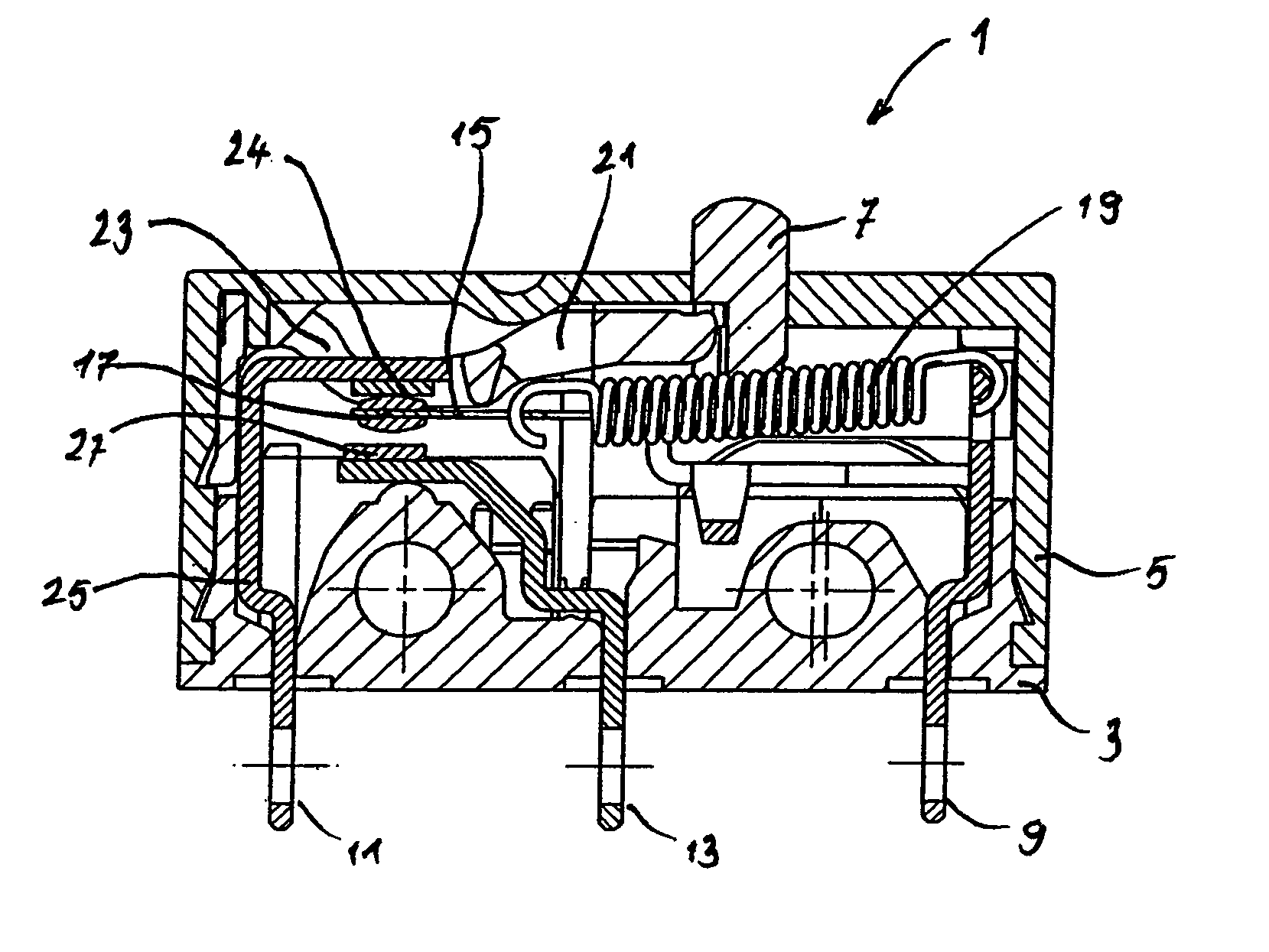
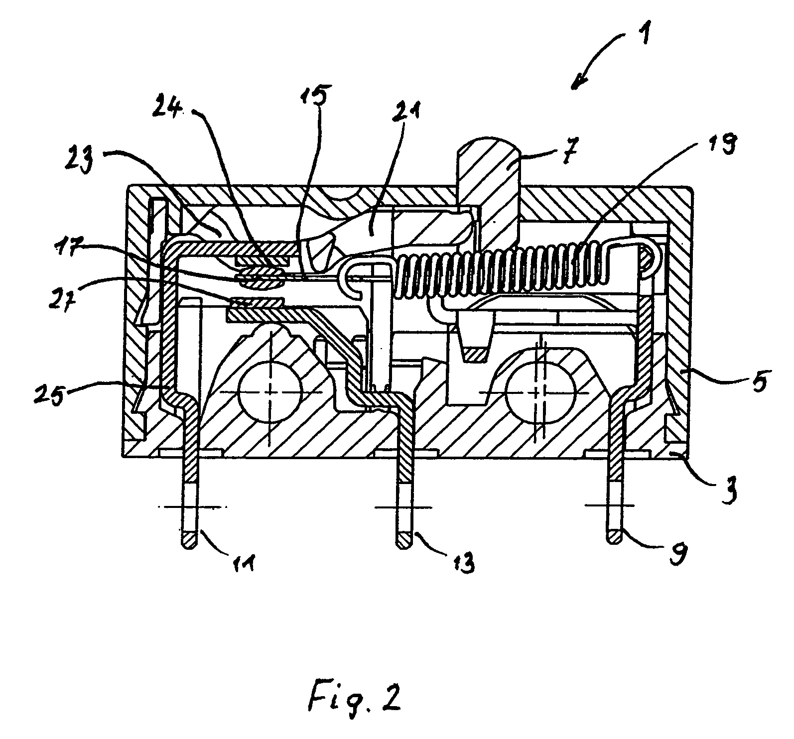
[0015]In this type of micro-switch, the actuator 7 is not centrally positioned, but offset to the right (in the present example). Via a tension spring 19, the actuator 7 pushes on a contact maker 15, which is moveably (in particular pivotably) supported and has two contacts 17 at its moveable end. The blade of the contact maker 15 is electrically connected to a common terminal 9 via a contact support (not shown). The contacts 17 form contact points with fixed contacts 24 and 27. The top fixed contact 24 is electrically connected to the terminal 11 via a connecting conductor 25; the bottom fixed contact 27 is correspondingly connected to the te...


PUM


Abstract

The invention relates to a sub-miniature switch including a housing, an actuator and terminals. The actuator protrudes from the housing at a position offset from the center of the housing. The terminals are electrically conductively coupled with fixed contacts (positioned within the housing). A contact maker is moved via the actuator and held in a first or second switching position by means of a bistable spring arrangement. An additional component, a separator or auxiliary actuator, is in snap-fit engagement with or clamped or glued in the cover of the housing and is pushed through by the actuator as the switch is operated. According to the present invention, the contact point of the fixed contacts is on a side of the housing which is opposite the actuator. The separator or auxiliary actuator is moved in the direction of the contact position by the actuator. Thus a structurally simple forced-opening capability is provided for the sub-miniature switch.

Description

BACKGROUND OF THE INVENTION[0001]The present invention relates to a sub-miniature switch of a type which is known in the state of the art, in particular from EP 618 603 B1 and GB 2 142 471 A.[0002]The sub-miniature switches according to the prior art have a housing with a cover, an actuator protruding from the housing, and external terminals. The actuator is offset from the center of the housing. The terminals are connected in an electrically conducting way with fixed contacts positioned inside the housing. A moveably supported, in particular rotatably supported, contact maker can take up two positions depending on the position of the actuator. In both the first and second switching positions, the contact maker is held by a bistable spring arrangement (tension spring).[0003]An additional component, a hold-down plate or separator or auxiliary actuator is provided in the housing, which is pushed through by the actuator as it is switched over from the first switching position to the se...

Claims


Application Information

Patent Timeline
Patent Type & Authority Patents(United States)
IPC IPC(8): H01H3/12
CPCH01H3/001H01H13/14H01H13/28
Inventor SCHOBER, THOMASREINDL, STEFAN
Owner ZF FRIEDRICHSHAFEN AG
Why Eureka
Try Eureka