Cap removing apparatus

a technology of cap and cap cap, which is applied in the direction of liquid handling, applications, instruments, etc., can solve the problem of liable long time period between correcting the posture of the cap and removing the cap from the test tub

Inactive Publication Date: 2007-04-24
IDS CO LTD
View PDF5 Cites 14 Cited by
  • Summary
  • Abstract
  • Description
  • Claims
  • Application Information

AI Technical Summary

Benefits of technology

[0012]An object of the present invention is to provide a cap removing apparatus, which can successfully remove a cap from a container.
[0015]With the apparatus described above, after correction of the posture of the knob, the container can be moved from the first position to the second position without changing the direction of the knob. Thus, the cap can be successfully removed from the container at the second position.
[0016]Moreover, in the cap removing apparatus according to the above aspect, an operation between correcting the posture of the knob of the cap and removing the cap from the container is speeded up as compared to that in the conventional cap removing apparatus using a belt conveyor.

Problems solved by technology

Therefore, a time period between correcting the posture of the cap and removing the cap from the test tube is liable to be long.

Method used


Image

  • Cap removing apparatus
  • Cap removing apparatus
  • Cap removing apparatus

Examples


Embodiment Construction

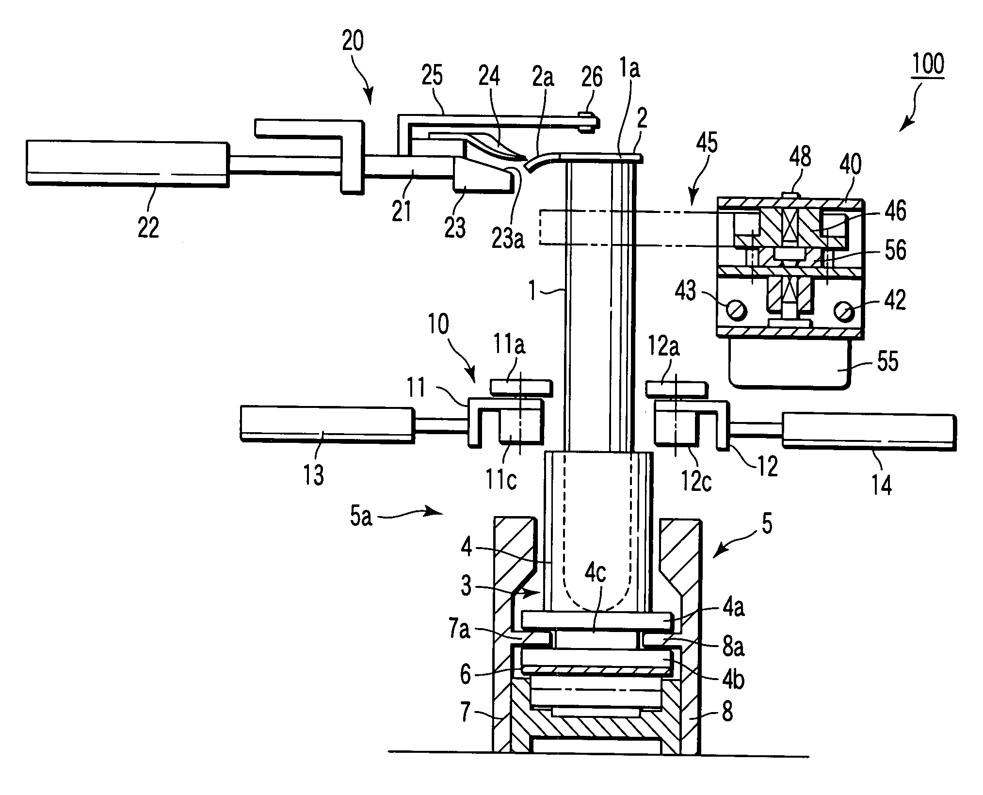
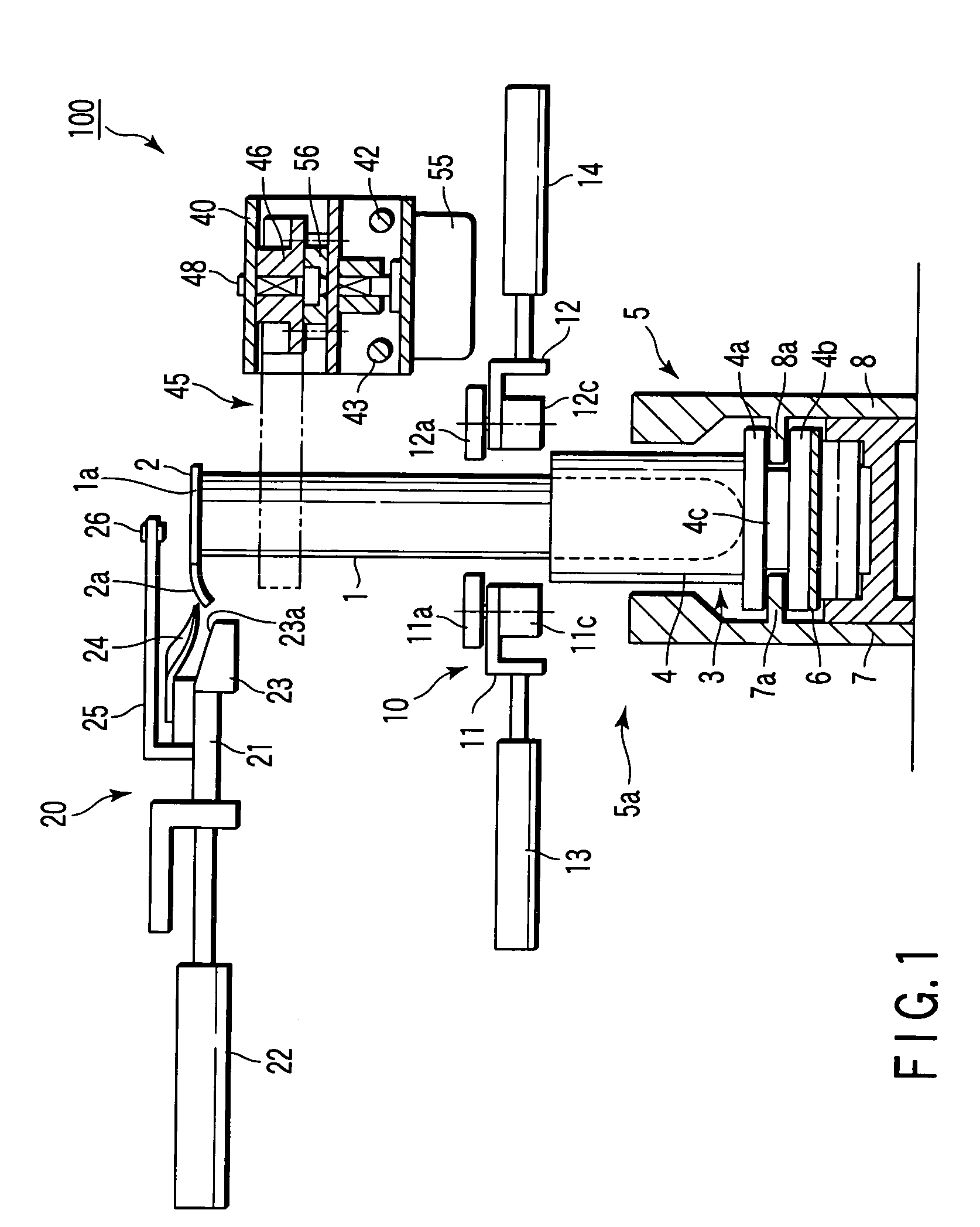
[0027]A cap removing apparatus 100 according to an embodiment of the present invention will be described with reference to the accompanying drawings.

[0028]In the drawings, a reference numeral 1 denotes a test tube. The test tube 1 is, for example, a container, at least a part of which is tube-like. The test tube 1 contains a sample, such as blood. The test tube 1 has an opening end 1a. The opening end 1a of the test tube 1 is closed by a cap 2, which is removable. The cap 2 is held to the opening end 1a of the test tube 1 by, for example, adhesive force. The peripheral portion of the cap 2 has a knob 2a, which is used when the cap 2 is to be removed from the test tube 1.

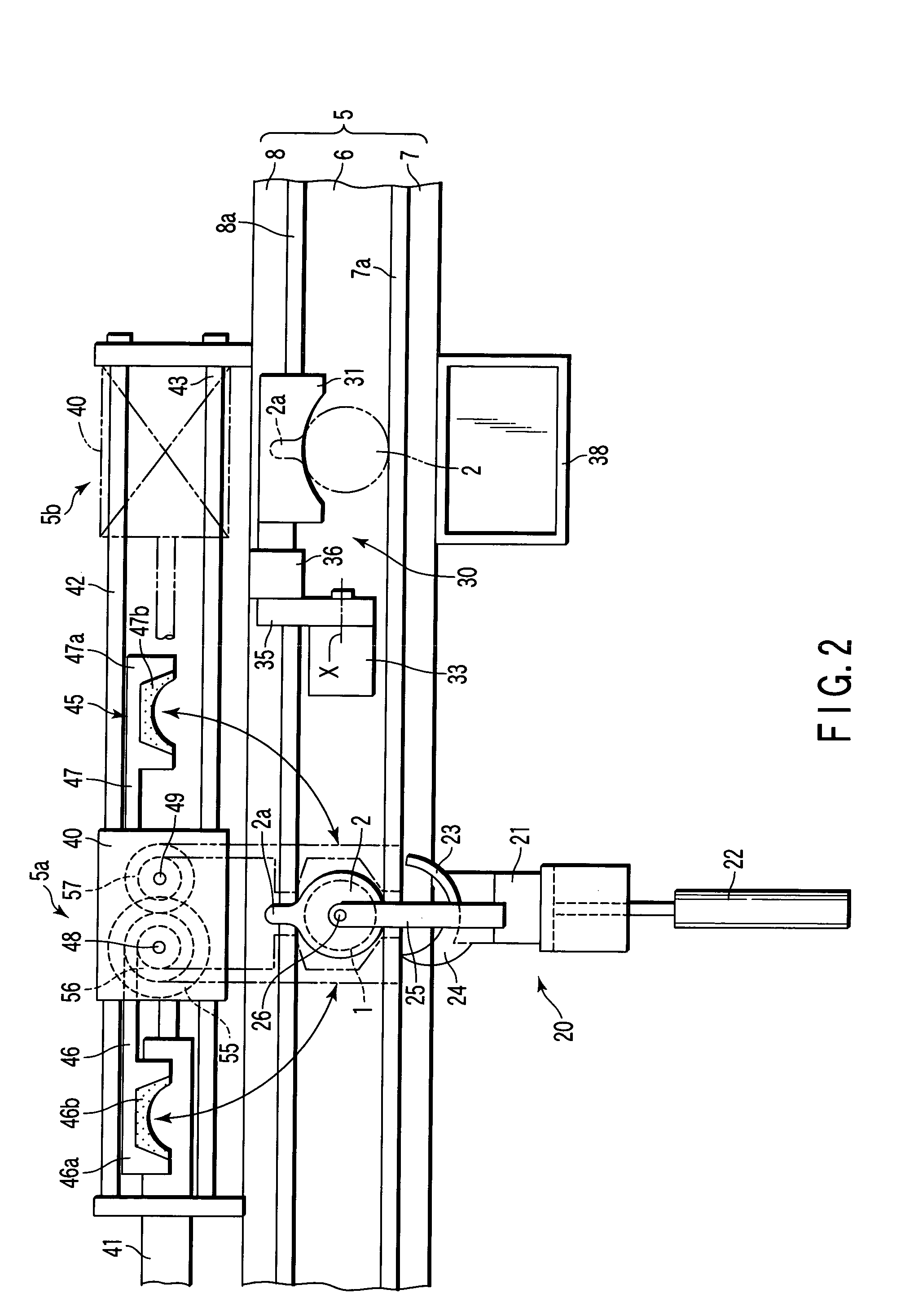
[0029]The test tube 1 is intermittently transferred in a predetermined direction through a transfer path 5 in a state where it is held in a vertical position by a test tube holder 3, which serves as a holding mechanism. As shown in FIG. 1, the test tube holder 3 has a cylindrical portion 4 in which the test tube 1 is...


PUM

PropertyMeasurementUnit
distanceaaaaaaaaaa
flexibilityaaaaaaaaaa
timeaaaaaaaaaa

Abstract

A cap removing apparatus includes a transfer path through which a container closed by a cap is transferred, a rotary driving mechanism provided in a first position and rotates the container, a correcting mechanism which corrects the posture of a knob of the cap, and a cap-removing mechanism which is provided in a second position, pinches the knob and removes the cap. A movable body, configured to move forward and backward between the first position and the second position, is provided on the transfer path. The movable body has a clamping mechanism. The clamping mechanism clamps the container with the cap whose knob has been posture-corrected in the first position, and moves the container from the first position to the second position. The clamping mechanism releases the clamping state at a time when the removal of the cap is completed, and returns to the first position.

Description

CROSS-REFERENCE TO RELATED APPLICATIONS[0001]This application is based upon and claims the benefit of priority from prior Japanese Patent Application No. 2004-129779, filed Apr. 26, 2004, the entire contents of which are incorporated herein by reference.BACKGROUND OF THE INVENTION[0002]1. Field of the Invention[0003]The present invention relates to a cap removing apparatus, which corrects the posture of a knob of a cap that closes an opening end of a container, such as a test tube containing a sample, and thereafter removes the cap from the container.[0004]2. Description of the Related Art[0005]A conventional cap removing apparatus, disclosed in Japanese Patent No. 2731729, automatically removes a cap from an opening end of a test tube. This conventional cap removing apparatus comprises a test tube holder, a belt conveyor, a rotary driving mechanism, a correcting mechanism and a cap-removing mechanism.[0006]The test tube holder holds a test tube with its opening end closed by a cap,...

Claims


Application Information

Patent Timeline
Patent Type & Authority Patents(United States)
IPC IPC(8): B67B7/00B67B7/16B65B35/16G01N35/02B65B35/58B67B7/12B67B7/40G01N35/04
CPCB67B7/00B67B7/40G01N35/021G01N2035/0405G01N35/04
Inventor ITOH, TERUAKI
Owner IDS CO LTD
Why Eureka
Try Eureka