Direction-limiting device for stroller

a technology of limiting device and stroller, which is applied in the direction of transportation and packaging, transportation/perambulator with multiple axes, manufacturing tools, etc., can solve problems such as injury to children in the stroller

Inactive Publication Date: 2007-05-01
TAN YI CHENG
View PDF21 Cites 40 Cited by
  • Summary
  • Abstract
  • Description
  • Claims
  • Application Information

AI Technical Summary

Benefits of technology

[0012]When the press button is in an initial position, some of the protruded guiding sections are received in the grooves of the sleeve and the other protruded guiding sections are superimposed on the protrusions of the sleeve. The apex of each guide rib is accommodated in an associated one of the downwardly facing grooves of the press button. The lower end of the positioning member is disengaged from the positioning hole of the wheel assembly to allow free pivotal movement of the wheel assembly relative to the base.
[0013]When the press button is pressed and then released, the rotary member is moved downward and turned in a direction. The apex of the slanted top face of each guide rib of the rotary member moves across the slanted bottom face of an associated one of the ribs to the bottom retaining edge of an associated one of the protrusions adjacent to the associated rib under the action of returning force of the second elastic member. The lower end of the positioning member is engaged in the positioning hole of the wheel assembly, allowing joint movement of the wheel assembly and the base. Thus, even moving on a rugged road or hitting a bump on a road, the stroller will move straightly forward or rearward without the risk of turning over.

Problems solved by technology

However, in a case that the stroller is moving rectilinearly on a rugged road or hits a bump on a road at a high speed, the stroller may turn suddenly and thus turn over, leading to injury to the child in the stroller.

Method used


Image

  • Direction-limiting device for stroller
  • Direction-limiting device for stroller
  • Direction-limiting device for stroller

Examples


Embodiment Construction

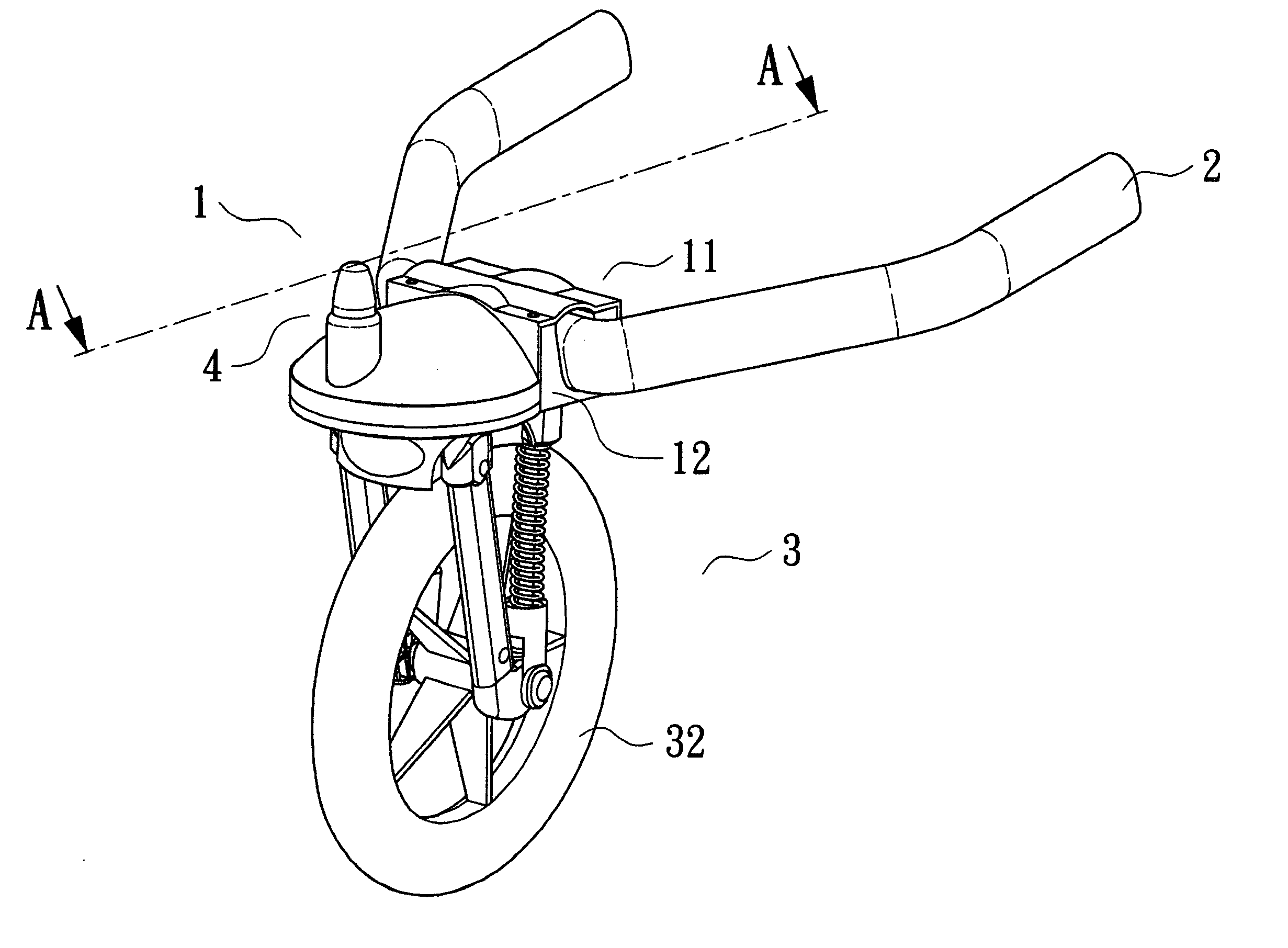
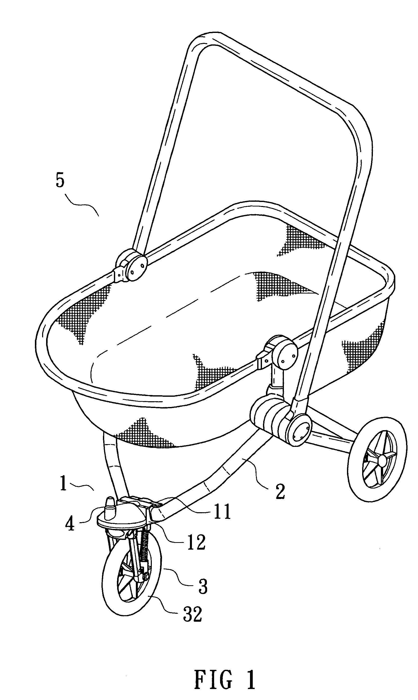
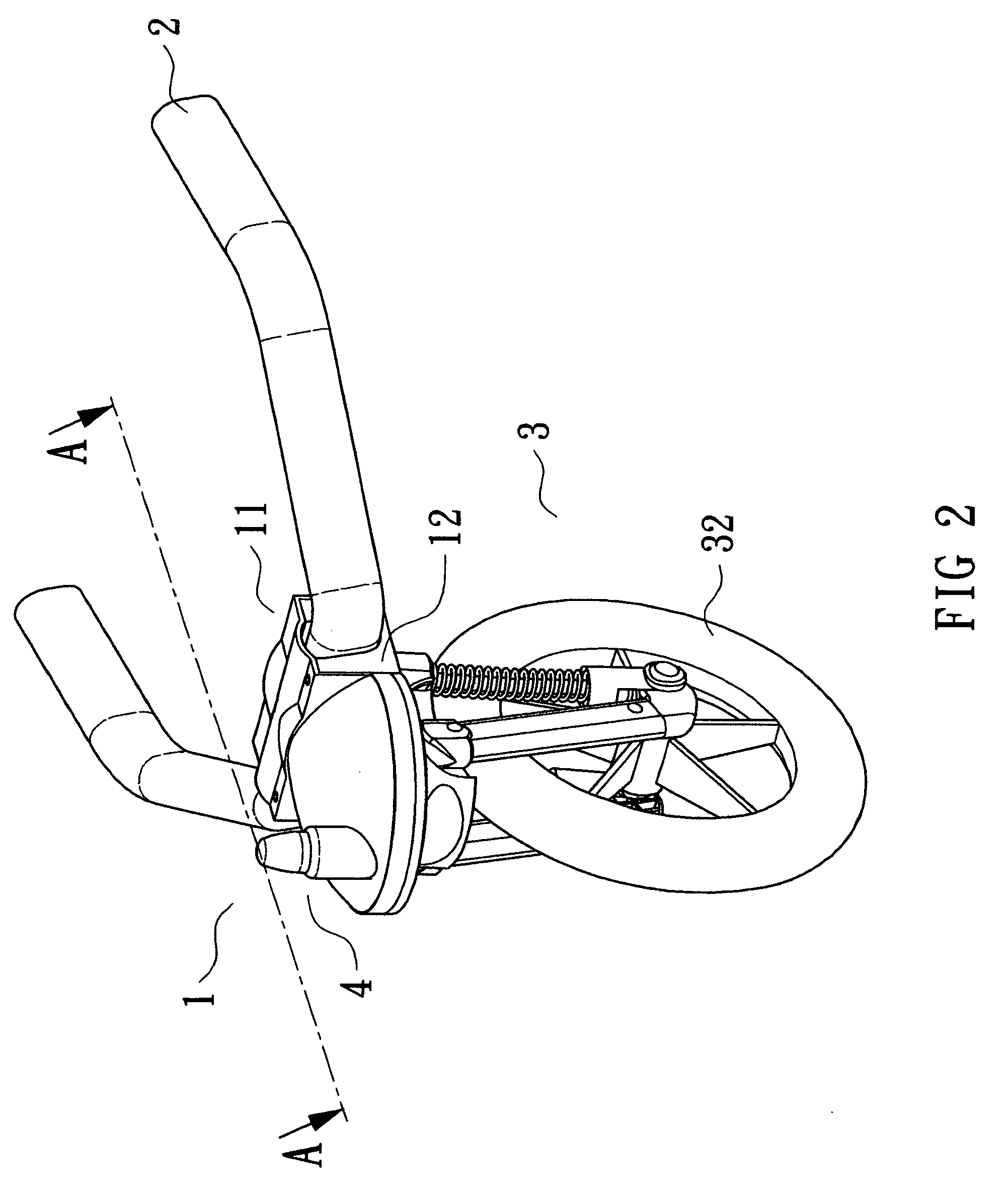
[0036]Referring to FIGS. 1 and 2, a direction-limiting device in accordance with the present invention is mounted to a stroller 5 and comprises a mounting seat 1 attached to front ends of two extension rods 2 that form a part of a frame of the stroller 5. As illustrated in FIGS. 2 and 3, the mounting seat 1 comprises a base 12 for coupling with the front ends of the extension rods 2. In the illustrated embodiment, the front ends of the extension rods 2 are integrally formed with each other. The base 12 includes a holed seat 121 with a vertical hole 120 and a through-hole 122 adjacent to the holed seat 121 and extending in a direction parallel to the vertical hole 120. A key groove 123 is defined in an inner periphery of the holed seat 121. As illustrated in FIG. 8, the holed seat 121 includes a shoulder 124 in a lower end thereof. The mounting seat 1 further comprises a cover 11 removably mounted on top of the base 12 and having a hole 111.

[0037]Referring to FIGS. 2 and 5, the direc...


PUM


Abstract

A direction-limiting device for a stroller includes a mounting seat, a wheel assembly, and a direction-limiting device. The mounting seat includes a base coupled to a frame of a stroller. The wheel assembly includes a frame having a positioning hole. The direction-limiting mechanism includes a press button and a positioning member. When the press button is in an initial position, a lower end of the positioning member is disengaged from the positioning hole to allow free pivotal movement of the wheel assembly relative to the base. When the press button is pressed and then released, the lower end of the positioning member is engaged in the positioning hole, allowing joint movement of the wheel assembly and the base. Thus, even moving on a rugged road or hitting a bump on a road, the stroller will move straightly forward or rearward without the risk of turning over.

Description

BACKGROUND OF THE INVENTION[0001]1. Field of the Invention[0002]The present invention relates to a direction-limiting device. In particular, the present invention relates to a direction-limiting device for a stroller or the like.[0003]2. Description of the Related Art[0004]A stroller is convenient to users having a child for outdoor activities. A typical stroller comprises a pivotable wheel assembly to allow steering of the stroller. However, in a case that the stroller is moving rectilinearly on a rugged road or hits a bump on a road at a high speed, the stroller may turn suddenly and thus turn over, leading to injury to the child in the stroller.SUMMARY OF THE INVENTION[0005]A direction-limiting device for a stroller in accordance with the present invention comprises a mounting seat, a wheel assembly, and a direction-limiting device. The mounting seat comprises a base coupled to a frame of a stroller. The base comprises a holed seat and a through-hole. The holed seat includes a sh...

Claims


Application Information

Patent Timeline
Patent Type & Authority Patents(United States)
IPC IPC(8): B60B33/02B62B7/04
CPCB60B1/006B60B33/0018B60B33/0049B60B33/0068B60B33/0073B60B33/025B60B33/045B62B7/04B62B9/18B60B33/0007Y10T16/195B62B7/044B62B7/062B62B2301/0463B62B2301/05B62B2301/20
Inventor TAN, YI-CHENG
Owner TAN YI CHENG
Why Eureka
Try Eureka