Pocket former

a technology of concrete and pockets, applied in the field of pockets formers, can solve the problems of occasional leakage of concrete between the second rim and the second rim, and achieve the effect of improving surface geometry and promoting grout adhesion

Inactive Publication Date: 2007-05-15
LOMONT MOLDING
View PDF9 Cites 22 Cited by
  • Summary
  • Abstract
  • Description
  • Claims
  • Application Information

AI Technical Summary

Problems solved by technology

This often causes serious damage to the pocket former making them non-reusable.
Additionally, during concrete placement, concrete occasionally leaks between the second rim of the pocket former and the concrete form.

Method used


Image

  • Pocket former
  • Pocket former
  • Pocket former

Examples


Embodiment Construction

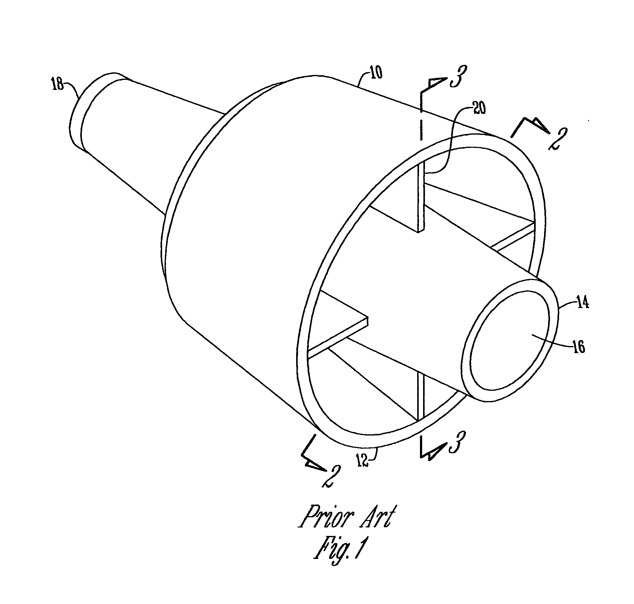
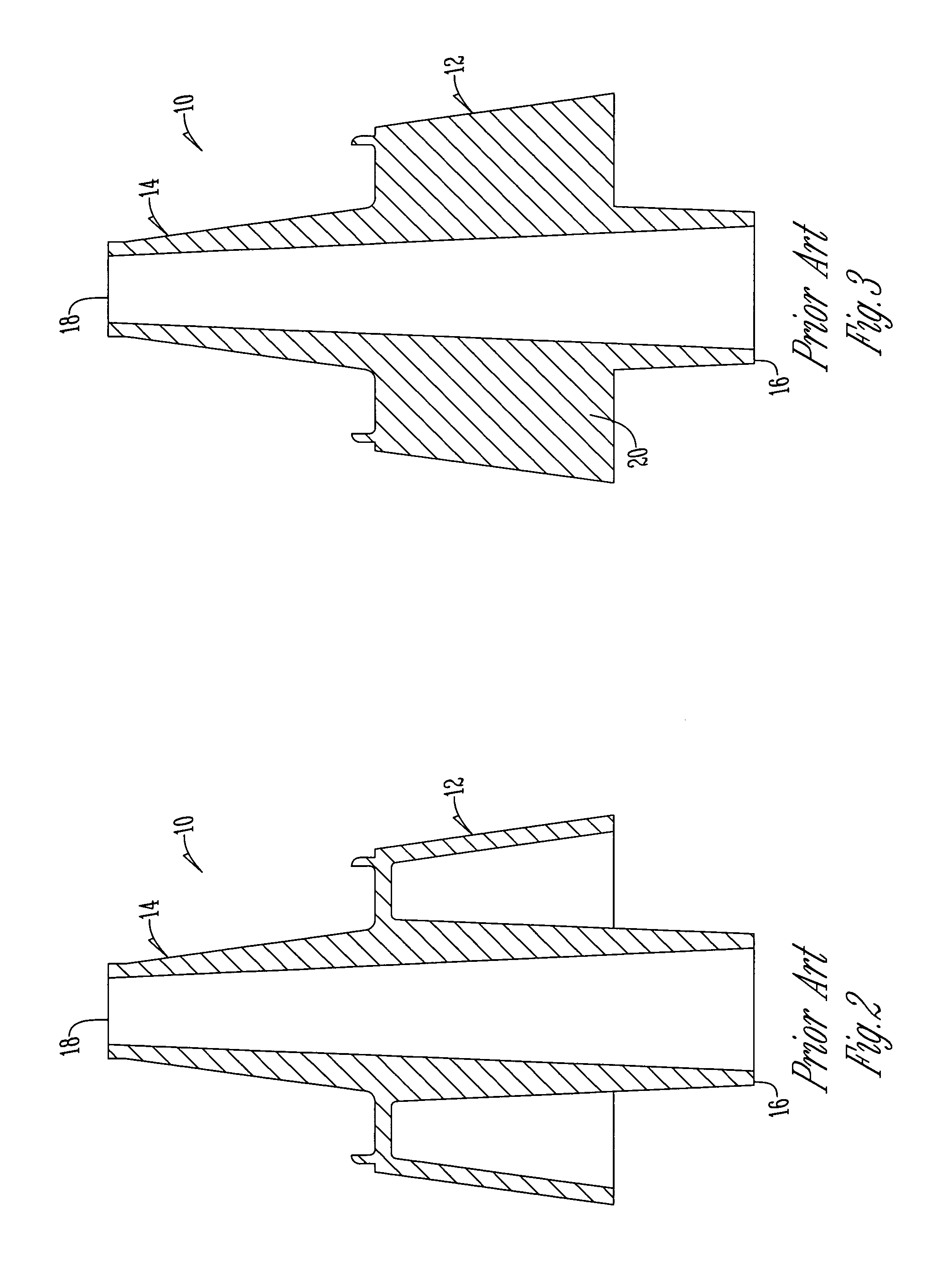
[0018]Referring to FIGS. 1–3, there is shown the conventional prior art pocket former 10. The conventional pocket former 10 includes a body portion 12 with a tubular member 14 extending therethrough. The body portion 12 has a generally frustoconical configuration. The tubular member 14 extends centrally through the frustoconical configuration of the body portion 12. The tubular member 14 is generally tapered from end 16 downwardly toward end 18. The tubular member 14 serves to allow a cable to extend centrally therethrough. Similarly, the body portion 12 is tapered downwardly in the direction toward end 18. A plurality of struts 20 extend between the tubular member 14 and the inside of the body portion 12.

[0019]Unfortunately, the configuration of the pocket former 10 of the prior art does not facilitate the ability to remove the pocket former 10 after concrete has cured. The prior art method of removing the pocket former 10 is usually done by gripping the struts 20 and pulling or pr...


PUM

PropertyMeasurementUnit
strengthaaaaaaaaaa
residual tensionaaaaaaaaaa
tinsel strengthaaaaaaaaaa

Abstract

A pocket former includes an outer barrel having a first rim, a second rim and a frustoconical body portion extending from the first rim to the second rim. A center barrel is connected to the outer barrel and has a proximal lip adjacent the first rim of the outer barrel, a distal lip adjacent the second rim of the outer barrel, and a tubular body portion extending from the proximal lip to the distal lip, and extends beyond both the first rim and the second rim. An annular flange curves out and away from the second rim of the outer barrel. A spiral surface is located on the frustoconical body portion of the outer barrel. A nut surface is located on the tubular body portion of the center barrel adjacent the distal lip.

Description

BACKGROUND OF THE INVENTION[0001]The present invention relates to the field of post-tensioning concrete structures, and the methods and apparatus for forming the same. More particularly, the invention relates to a pocket former and methods of forming a pocket surface for assembling a post-tensioning concrete structure.[0002]Post-tensioning is a process where high strength cables are embedded in concrete and tensioned after the concrete cures. The residual tension that is retained in the cable increases the tinsel strength of the finished concrete structure. Cable ends are secured within the concrete with specially designed steel anchors. Cable assemblies are pre-manufactured specifically for a given job. The cable assemblies include a complete assembled anchor on the “dead end” and a “free end” that is assembled on the job site.[0003]The free end assembly is comprised of a standard anchor to transfer cable tension to the concrete, tapered retainer keys to secure the cable to the anc...

Claims


Application Information

Patent Timeline
Patent Type & Authority Patents(United States)
IPC IPC(8): B28B7/28B28B21/60B28B23/06
CPCB28B7/28E04C5/12E04G15/063B28B23/046
Inventor WATSON, VIRGIL ALLEN
Owner LOMONT MOLDING
Why Eureka
Try Eureka