Support mechanism

a technology of supporting mechanism and seat, which is applied in the direction of chair, machine support, and cabin floor fastening, etc., can solve the problems of cumbersome mechanism for such movable boat seats, unnecessarily large space on the boat's deck, and difficulty in adjustmen

Inactive Publication Date: 2007-05-29
WELKER ORVILLE V
View PDF16 Cites 12 Cited by
  • Summary
  • Abstract
  • Description
  • Claims
  • Application Information

AI Technical Summary

Problems solved by technology

However, many prior art fishing boat seats, which are movable between such deployed and stowed positions, occupy an unnecessarily large amount of space on the boat's deck, leaving less room for fishing gear, etc.
Moreover, in many cases, the support mechanisms for such movable boat seats are cumbersome and difficult to adjust between deployed and stowed positions, which is particularly undesirable in an environment where balance is already a challenge.

Method used


Image

  • Support mechanism
  • Support mechanism
  • Support mechanism

Examples


Embodiment Construction

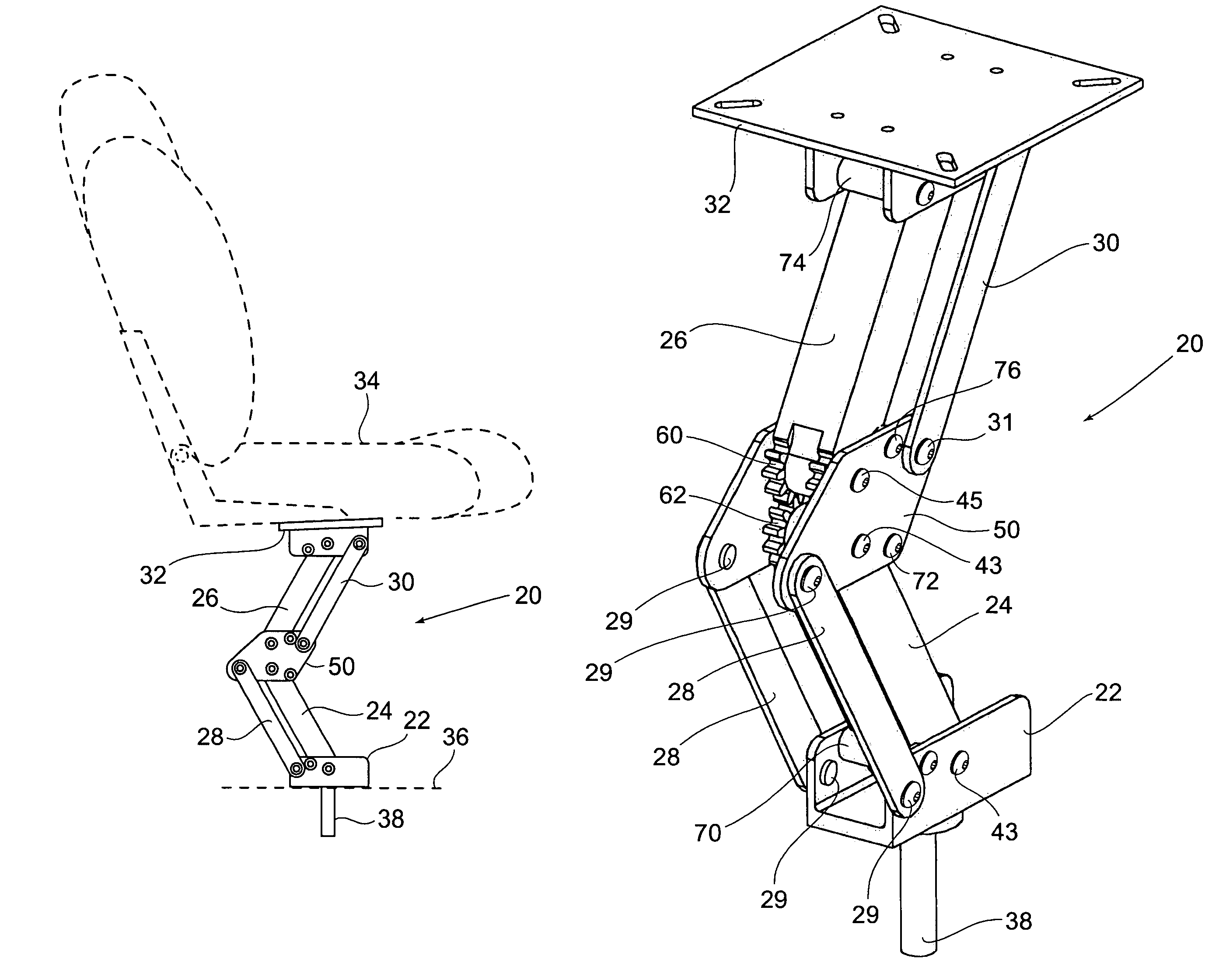
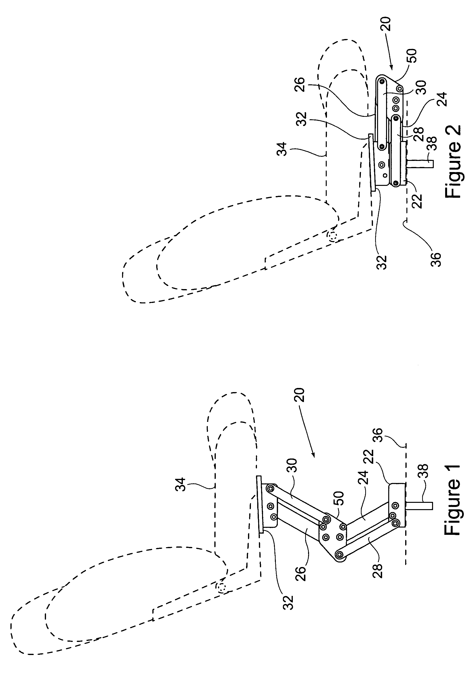
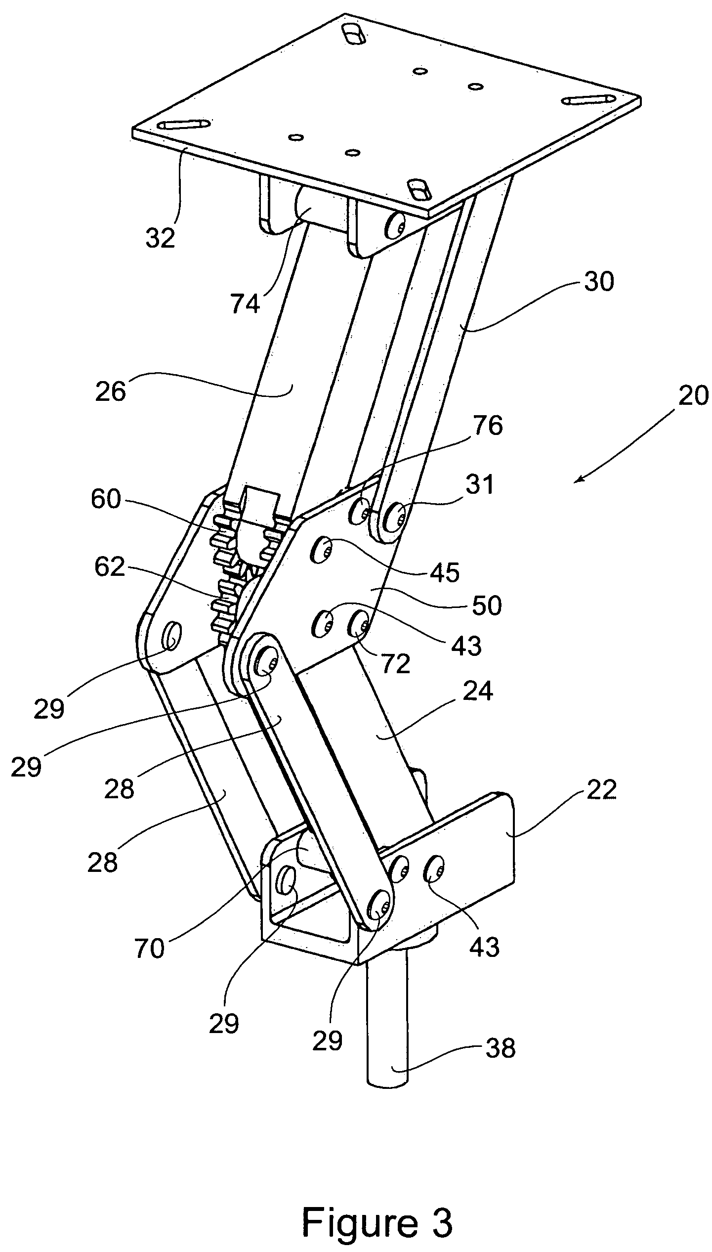
[0022]A boat seat support mechanism of the present invention is represented generally by the reference numeral 20 in FIGS. 1–4. The support mechanism 20 comprises a base member or pedestal 22, a lower support arm 24, an upper support arm 26, lower synchronizing arms 28, upper synchronizing arms 30, and a load-supporting platform 32. FIGS. 1 and 2 also include broken line representations of a seat 34 and a support surface 36 (e.g., a boat deck), to illustrate an environment in which the present invention may be used. As explained below in more detail, the support mechanism 20 is movable between a deployed position (shown in FIG. 1), wherein the seat 34 is elevated above the support surface 36, and a stowed position (shown in FIG. 2), wherein the seat 34 is lowered and generally adjacent the support surface 36.

[0023]The base member 22 is adapted for supporting the support mechanism 20 from the support surface 36. As shown in FIGS. 3, 4 and 7, the base member preferably includes a gene...


PUM


Abstract

A support mechanism comprises a base member, first and second support arms, first and second synchronizing arms, and a load-supporting platform. The first support arm is connected to a pivot bracket and the based member in a manner to permit pivoting movement of the first support arm between stowed and deployed positions. The second support arm is connected to the pivot bracket and the load-supporting platform in a manner to permit pivoting movement of the second support arm relative to the load-supporting platform between stowed and deployed positions. The first and second synchronizing arms are also operatively connected to the based member, pivot bracket and load-supporting platform in a manner so that the first synchronizing arm and first support arm maintain a substantially parallel relationship with one another throughout the entire range of movement of the first support arm, and so that the second synchronizing arm and second support arm also maintain a substantially parallel relationship with one another throughout the entire range of movement of the second support arm.

Description

BACKGROUND OF THE INVENTION[0001]This invention relates to support mechanisms and, more particularly, to seat-support mechanisms adapted for use with fishing boat seats. It is known in the art to provide fishing boat seats, which are movable between a deployed position (i.e., a generally elevated position) for use while fishing from the boat and a stowed position (i.e., a generally lowered position) for use while operating the boat. A deployed seat position, which is generally elevated from the boat's deck, is desirable because it provides the fisherman with an optimal view of his surroundings and more unobstructed space for operating fishing gear. A stowed position, in which the seat is generally adjacent the boat's deck, is desirable during operation of the boat, because it provides a lower center of gravity and greater stability while the boat is moving.[0002]However, many prior art fishing boat seats, which are movable between such deployed and stowed positions, occupy an unnece...

Claims


Application Information

Patent Timeline
Patent Type & Authority Patents(United States)
IPC IPC(8): F16M13/00A47C3/20A47C1/02A47C3/38A47C9/10
CPCA47C3/38A47C15/004B63B29/04B63B29/06
Inventor WELKER, ORVILLE V.
Owner WELKER ORVILLE V
Why Eureka
Try Eureka