Board-mounted electrical connector with balanced solder attachment to a circuit board

a technology of balanced solder attachment and circuit board, which is applied in the direction of securing/insulating coupling contact members, coupling device connections, printed circuits, etc., can solve the problems of electrical connector deformation, electrical connector unbalanced soldering intensity, and affect normal signal transmission, so as to achieve reliable signal transmission of the whole electrical connector

Inactive Publication Date: 2007-05-29
HON HAI PRECISION IND CO LTD
View PDF14 Cites 4 Cited by
  • Summary
  • Abstract
  • Description
  • Claims
  • Application Information

AI Technical Summary

Benefits of technology

[0006]Accordingly, an object of the present invention is to provide an electrical connector having balanced soldering intensity so as to be securely assembled onto a printed circuit board and ensure a reliable signal transmission of the whole electrical connector.

Problems solved by technology

When the power and signal terminals are distributed asymmetrically in the electrical connector and the electrical connector is mounted onto a printed circuit board, the electrical connector will have unbalanced soldering intensity.
Consequently, the soldering area between the signal terminal and the printed circuit board is easily broken off when the electrical connector repeatedly connects with / detaches from a complementary connector or due to an accidental external force, thereby resulting in deformation of the electrical connector and even leading to break the electrical interconnection between the electrical connector and the printed circuit board and thus affect normal signal transmission.

Method used


Image

  • Board-mounted electrical connector with balanced solder attachment to a circuit board
  • Board-mounted electrical connector with balanced solder attachment to a circuit board
  • Board-mounted electrical connector with balanced solder attachment to a circuit board

Examples


Embodiment Construction

[0016]Reference will now be made in detail to the preferred embodiment of the present invention.

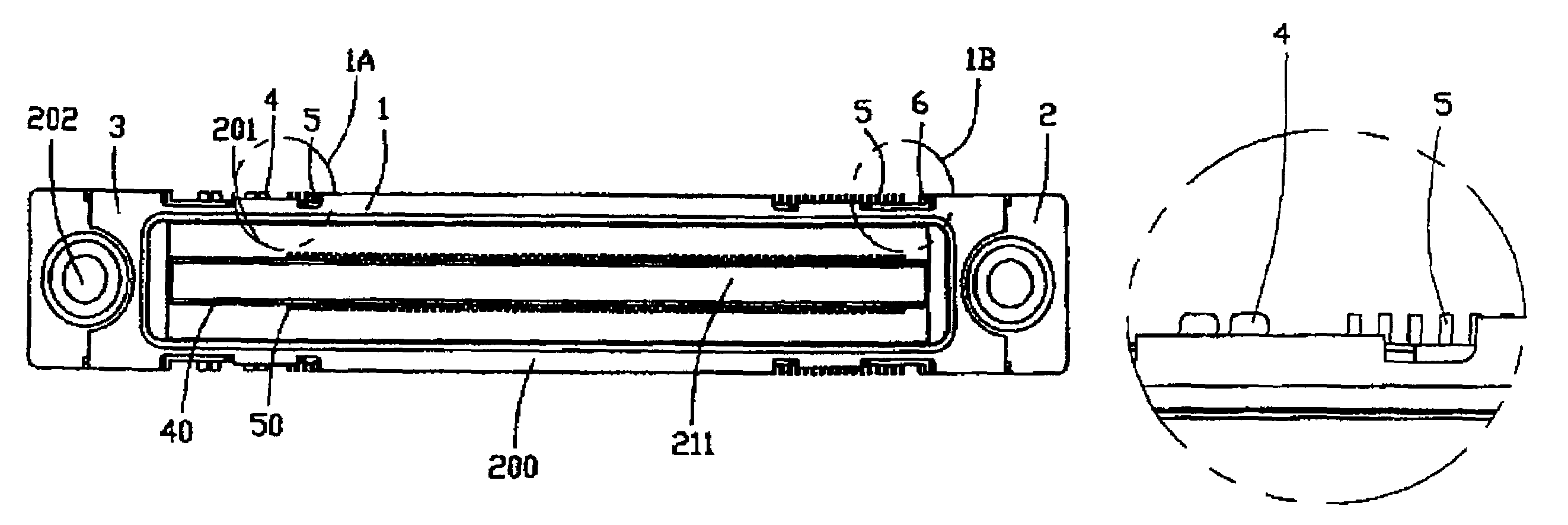
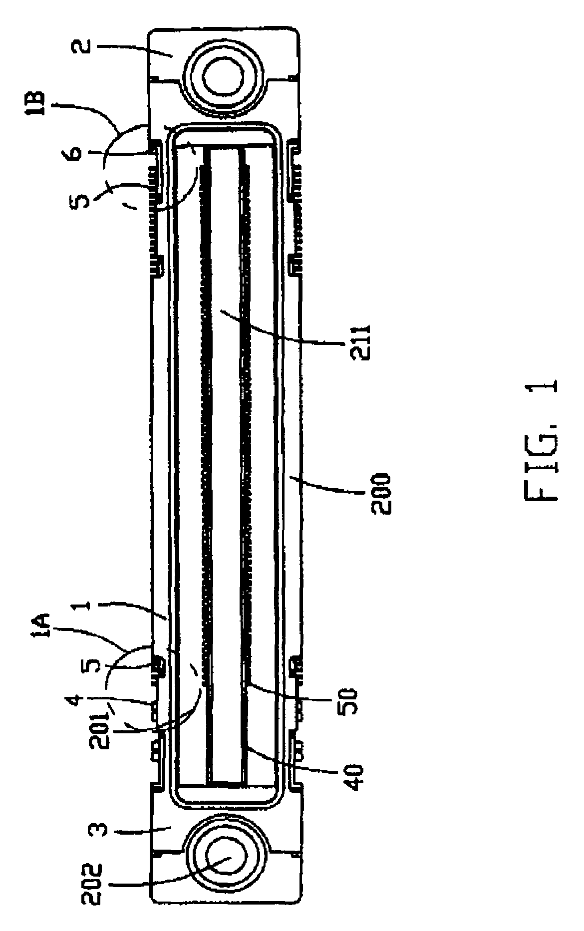
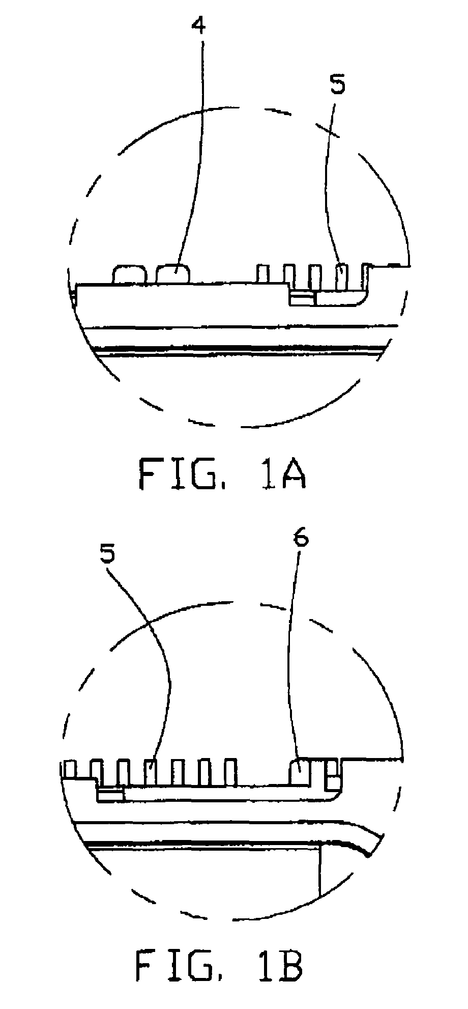
[0017]Referring to FIG 1, an electrical connector 1 in accordance with the present invention comprises a dielectric housing 2, a shielding shell 3 attached on the dielectric housing 2, a plurality of power terminals 4, signal terminals 5, and solder pad contacts 6 received in the dielectric housing 2.

[0018]Referring to FIGS. 1 to 3 in conjunction with FIGS. 4 and 5, the dielectric housing 2 is rectangular and comprises a base portion 20 and a bottom portion 21 integrally connecting with the base portion 20. The base portion 20 has a mating surface 200 for mating with a complementary connector (not shown) and the bottom portion 21 has an engaging surface 210 parallel to and for mounting to a top surface of a printed circuit board (not shown). The base portion 20 defines an elongated plug-receiving chamber 201 and the chamber 201 is divided longitudinally by a central partition 211 projecti...


PUM


Abstract

An electrical connector (1) includes a dielectric housing (2), a number of power terminals (4) at one end of the housing, signal terminals (5) and solder pad contacts (6) disposed at the other end of the housing opposite to the power terminals. The housing includes a base portion (20) and a bottom portion (21) and defines a number of passageways (212, 213, 215) extending through the bottom portion. The terminals (4, 5) received in the passageways (212, 213) each have a contact portion (40, 50) and a solder foot (41, 51). The solder pad contacts and the power terminals have a width greater than the signal terminals. The solder pad contacts are upwardly inserted into the passageways (215) of the base portion from the bottom portion and each includes a retention portion (60) for interfering with the base portion and a solder foot (61) extending beyond the bottom portion. Use of wide power terminals and wide solder pad contacts at the other end of the housing provides balanced solder attachment to a pcb. The solder pad contacts are used solely for securement to the pcb.

Description

BACKGROUND OF THE INVENTION[0001]1. Field of the Invention[0002]The present invention is related to an electrical connector, and more particularly to a board-mounted electrical connector for use in a notebook computer.[0003]2. Description of Related Art[0004]An electrical connector mostly comprises a dielectric housing and a plurality of conductive terminals received in the dielectric housing. The plurality of conductive terminals generally include power terminals, signal terminals and grounding terminals. Generally, the power terminal has a width greater than the signal terminal and the grounding terminal for the electrical current that the power terminals conduct is larger than that of the signal terminals. However, because the width of the power terminal is added, the soldering portion of the power terminal has higher soldering intensity than the signal terminal. When the power and signal terminals are distributed asymmetrically in the electrical connector and the electrical conn...

Claims


Application Information

Patent Timeline
Patent Type & Authority Patents(United States)
IPC IPC(8): H01R12/00H01R12/57H01R12/71H01R13/40
CPCH01R12/716
Inventor MAO, YU HUA
Owner HON HAI PRECISION IND CO LTD
Why Eureka
Try Eureka