Traction engine data transmitting system

A technology of transmission system and tractor, applied in the field of tractor data transmission system, can solve problems such as increased cost, non-action of tractor, and increase in the number of slip-out lines, etc.

Active Publication Date: 2007-08-22
CHINA NAT HEAVY MACHINERY RES INSTCO
View PDF0 Cites 3 Cited by
  • Summary
  • Abstract
  • Description
  • Claims
  • Application Information

AI Technical Summary

Problems solved by technology

However, due to the poor contact between the slide-out line and the contact in the currently used slip-out line data transmission form, the tractor will not operate or malfunction. At the same time, the increase in the control points of the tractor will increase the number of slide-out lines and increase the cost.

Method used


Image

  • Traction engine data transmitting system

Examples


Embodiment Construction

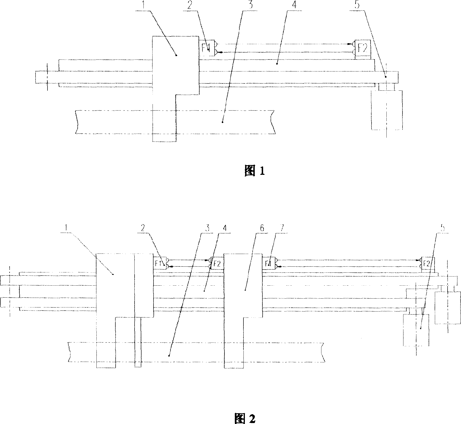
[0016] As shown in Figure 1, for a single tractor, the tractor guide rail 4 is arranged on the frame, and No. I tractor head 1 is slidably connected on the tractor guide rail 4, and No. I tractor head 1 is vertically arranged on the traction machine. On the tractor guide rail 4, the aluminum profile 3 is connected below No. I tractor head 1; one end of the tractor guide rail 4 is connected with the tractor driving device 5; the frame is provided with a data transmission photoelectric sensor, and the data transmission photoelectric sensor has two The first pair of data transmission photoelectric sensors 2 are installed on the right side above the active tractor nose 1, move together with the tractor nose 1, and are electrically connected to the distribution station on the tractor nose 1; the other The second pair of data transmission photoelectric sensors 7 are fixed above one end of the tractor guide rail 4, and are electrically connected with the central processing unit PLC of...


PUM


Abstract

The present invention relates to traction data transmitting system, and is especially traction engine data transmitting system for continuous extrusion of large aluminum material. In the traction engine frame, there are traction engine head on the tracks, aluminum section connected to the lower part of the traction engine and traction engine driving unit connected to the tracks. The present invention features the paired data transmitting photoelectronic sensors connected to the traction engine head. Of each pair of photoelectronic sensors, one is connected electrically to the distributed station of the traction engine head and the other is connected electrically to the PLC in the CPU of the output system. This kind of traction data transmitting system is reliable, and able to complete great amount of data transmission in low cost.

Description

technical field [0001] The invention belongs to a traction data transmission system for extruded products, in particular to a tractor data transmission system for continuous extrusion of large aluminum profiles. Background technique [0002] In the extrusion production of aluminum profiles, tractors are needed to eliminate the uneven flow of aluminum profiles along the cross-section at the die mouth. For continuous extrusion production, dual traction devices are usually used. The tractor moves back and forth along the traction track, and transmits data to the tractor moving back and forth through the slide-out line, so that the tractor can accept the control of the central PLC of the entire post-processing system and realize synchronization with the extrusion machine. However, due to the poor contact between the slide-out line and the contact in the currently used slip-out line data transmission form, the tractor does not operate or malfunctions. At the same time, the increa...

Claims


Application Information

Patent Timeline
Patent Type & Authority Applications(China)
IPC IPC(8): B21C31/00B21C35/02
Inventor 张君韩炳涛王宏亮徐星李振利
Owner CHINA NAT HEAVY MACHINERY RES INSTCO
Why Eureka
Try Eureka