Rotary joint

a rotary joint and rotary technology, applied in the field of rotary joints, can solve the problems of data only being transmitted, unsuitable for transmitting signals, optical rotary joints embodied in a standard commercially available configuration, etc., and achieve the effect of high transmission reliability and high level of transmission reliability

Inactive Publication Date: 2010-02-18
SIEMENS AG
View PDF2 Cites 3 Cited by
  • Summary
  • Abstract
  • Description
  • Claims
  • Application Information

AI Technical Summary

Benefits of technology

[0016]It furthermore proves advantageous for the transmitter to be connected to an end face of the first hollow body by way of a plurality of optical waveguides for transmitting the light signal. As a result of this measure only at least one single transmitter is necessary in the case of a unidirectional transmission while at the same time a high level of transmission reliability is assured.
[0017]It also proves advantageous for the optical waveguides to be connected to an end face of the first hollow body by means of connectors uniformly distributed over the end face. A continuous transmission of the data is ensured by means of this measure.
[0018]It also proves advantageous for the rotary joint to have a first transmitter for generating a first light signal and a second transmitter for generating a second light signal, wherein the rotary joint has a first receiver for receiving the first light signal and a second receiver for receiving the second light signal, wherein the first light signal can be transmitted from the first transmitter to the first receiver by way of the first and the second hollow body, wherein the second light signal can be transmitted from the second transmitter to the second receiver by way of the second and the first hollow body. This enables bidirectional data communication.
[0019]It also proves advantageous for the rotary joint to have a first transmitter for generating a first light signal and a second transmitter for generating a second light signal, wherein the rotary joint has a first receiver for receiving the first light signal and a second receiver for receiving the second light signal, wherein the first light signal can be transmitted from the first transmitter to the first receiver by way of the first hollow body, wherein the second light signal can be transmitted from the second transmitter to the second receiver by way of the second hollow body. This enables bidirectional data communication.
[0020]It furthermore proves advantageous for the first transmitter to be connected to an end face of the first hollow body by way of a plurality of optical waveguides for transmitting the first light signal, wherein the second transmitter is connected to an end face of the second hollow body by way of a plurality of further optical waveguides for transmitting the second light signal. As a result of this measure only at least two transmitters are necessary in the case of a bidirectional transmission while at the same time a high level of transmission reliability is assured.
[0021]It also proves advantageous for the optical waveguides to be connected to an end face of the first hollow body by means of connectors uniformly distributed over the end face of the first hollow body, wherein the further optical waveguides are connected to an end face of the second hollow body by means of connectors uniformly distributed over the end face of the second hollow body. A continuous transmission of the data is ensured by means of this measure.

Problems solved by technology

However said type of optical rotary joint embodied in a standard commercially available configuration is unsuitable for transmitting signals if the shaft is embodied as a hollow shaft, since the transmitter cannot be disposed in the axial center of rotation of the shaft but must be disposed on the hollow shaft outside the center of rotation, with the result that data can only be transmitted when the shaft and therefore the transmitter are in a specific angular position such that transmission to the receiver, which is likewise disposed outside the center of rotation, is possible.

Method used


Image

  • Rotary joint
  • Rotary joint
  • Rotary joint

Examples


Embodiment Construction

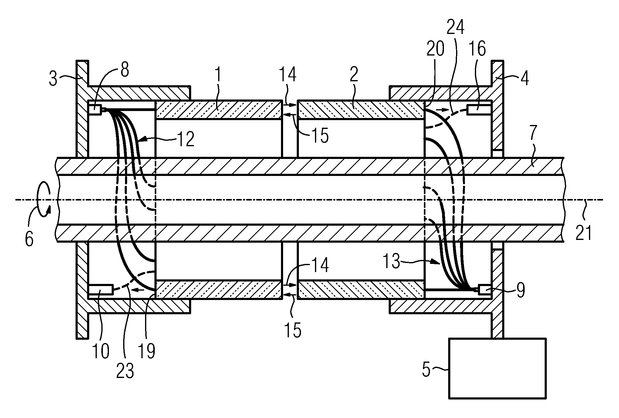
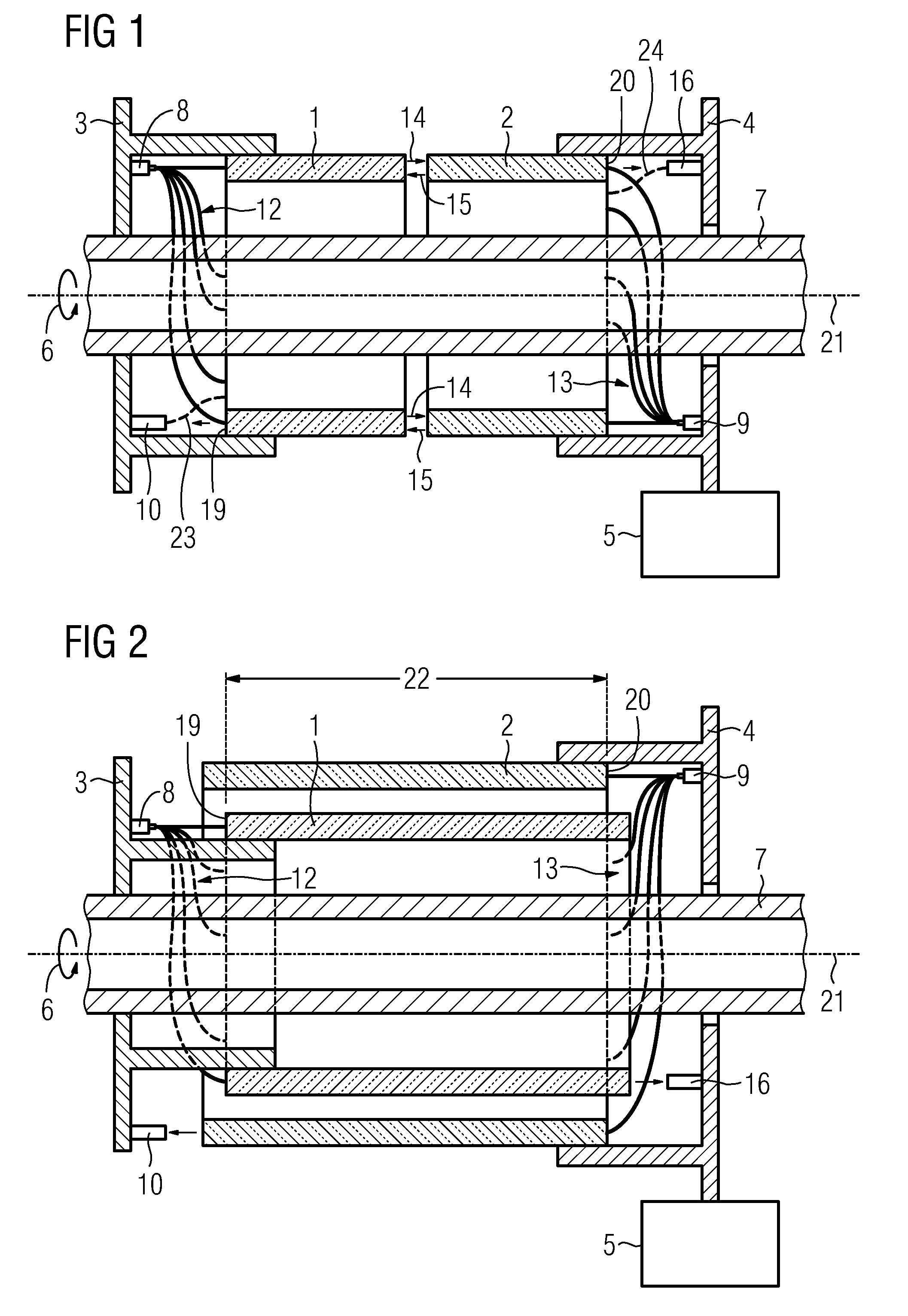
[0027]FIG. 1 shows a first embodiment of the rotary joint in the form of a schematic representation. In this case the rotary joint has a first housing part 3 which is fixedly connected to a rotating (see arrow 6) hollow shaft 7. The hollow shaft 7 can therein be present e.g. in the form of a motor shaft. As a result of the fixed connection of the first housing part 3 to the hollow shaft 7 the first housing part 3 co-rotates with the hollow shaft 7. In addition the rotary joint has a second stationary housing part 4 which is fixedly connected to a machine bed 5, e.g. a machine tool. The rotary joint also has a first light-conducting hollow body 1 and a second light-conducting hollow body 2. Within the scope of the exemplary embodiment the two hollow bodies are embodied as light-transmitting tubes, made e.g. of glass or Plexiglas. The first hollow body 1 is fixedly connected to the first housing part 3 and the second hollow body 2 is fixedly connected to the second housing part 4. In ...


PUM


Abstract

A rotary transmitter having a first light-conducting hollow body, at least one transmitter for generating at least one optical signal and at least one receiver for receiving the optical signal is disclosed. The optical signal is transmitted from the transmitter to the receiver via the first light-conducting hollow body.

Description

CROSS REFERENCE TO RELATED APPLICATIONS[0001]This application is the US National Stage of International Application No. PCT / EP2007 / 061183 filed Oct. 19, 2007 and claims the benefit thereof. The International Application claims the benefits of German Patent Application No. 10 2006 054 052.2 DE filed Nov. 16, 2006, both of the applications are incorporated by reference herein in their entirety.FIELD OF INVENTION[0002]The invention relates to a rotary joint.BACKGROUND OF INVENTION[0003]Rotary joints are used to transmit data from a rotating object, such as a shaft for example, to a stationary object, such as a closed-loop control module located in a switchgear cabinet.[0004]In the case of standard commercially available rotary joints the data is transmitted by means of slip rings for example.[0005]Also known are rotary joints in which data is transmitted from the rotating to the stationary part by means of optical signal transmission. In this case a transmitter disposed in the axial ce...

Claims


Application Information

Patent Timeline
Patent Type & Authority Applications(United States)
IPC IPC(8): H04B10/12H04B10/118
CPCG02B6/3604
Inventor KRAGL, HANSWETZEL, ULRICH
Owner SIEMENS AG
Why Eureka
Try Eureka