Knee-protecting airbag device

a technology for airbags and knees, which is applied in the direction of pedestrian/occupant safety arrangements, vehicular safety arrangments, vehicle components, etc., can solve problems such as airbag damage, and achieve the effect of convenient folding and complete deploymen

Inactive Publication Date: 2007-06-05
TOYODA GOSEI CO LTD
View PDF6 Cites 23 Cited by
  • Summary
  • Abstract
  • Description
  • Claims
  • Application Information

AI Technical Summary

Benefits of technology

[0009]The knee-protecting airbag device of the present invention protrudes rearward from the housing and rises while expanding when fed with inflation gas. At this time, even if the airbag contacts the key accessories hung down from the key inserted into the key cylinder, the airbag is able to complete deployment smoothly since the airbag is provided in a portion to contact the accessories with the reinforcing cloth, and the reinforcing cloth protects the airbag upon contacting the accessories. In addition, the airbag is folded easily, since the reinforcing cloth is flexible.
[0010]In the knee-protecting airbag device of the present invention, therefore, the airbag is able to protect the knees of driver securely since the airbag is protected by the reinforcing cloth, even if the deploying airbag contacts the accessories connected to the key.
[0012]With this arrangement, the airbag is protected whichever of the column side wall and the driver's side wall contacts the key accessories in airbag deployment. Therefore, the air bag is protected and thus is able to deploy stably even when, for example, a change of the folding method of the airbag or a change in behavior of the airbag cause a reversal of the part to contact the key accessories in the column side wall and the driver's side wall.
[0015]This arrangement is able to omit a separate stitching work of the reinforcing cloth to the column side wall and the driver's side wall. Therefore, the airbag having the reinforcing cloth is easily manufactured.

Problems solved by technology

If the airbag in this case deploys, lower ends of the accessories may contact an inflated part of the airbag, and damage the airbag.

Method used


Image

  • Knee-protecting airbag device
  • Knee-protecting airbag device
  • Knee-protecting airbag device

Examples


Embodiment Construction

[0035]Preferred embodiments of the present invention are now described below with reference to the accompanying drawings. However, the invention is not limited to the embodiments disclosed herein. All modifications within the appended claims and equivalents relative thereto are intended to be encompassed in the scope of the claims.

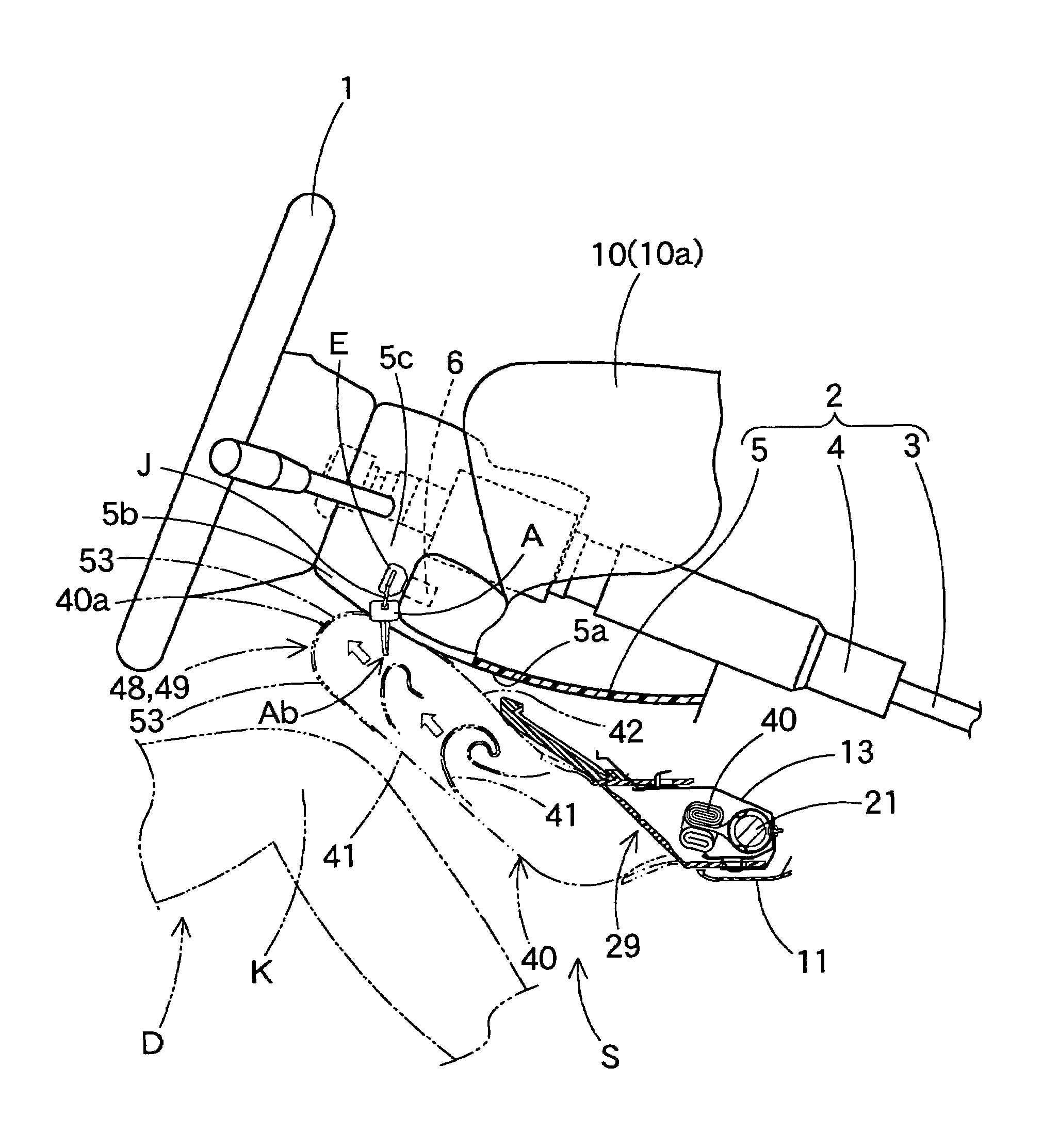
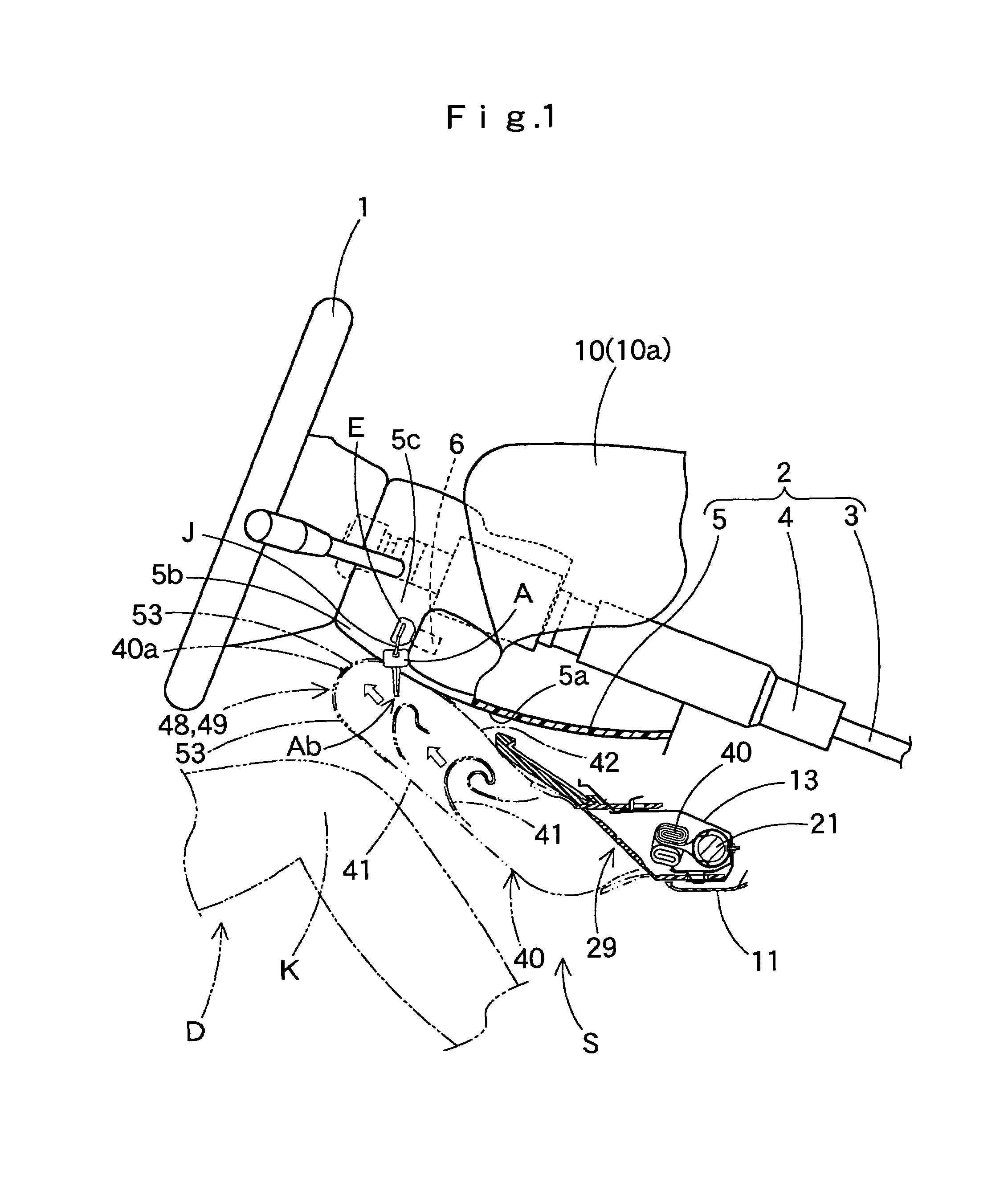
[0036]It is shown in FIGS. 1 and 8A that a knee-protecting airbag device S is located below the steering column 2 and in front of a driver D for protecting knees K of the driver D.

[0037]Up-down, front-rear, and left-right in this specification are based on a state in which the airbag device S is mounted on the vehicle, and therefore, correspond to up-down, front-rear, and left-right of the vehicle with the airbag device mounted thereon.

[0038]Referring to FIG. 1, the steering column 2 includes a main shaft 3 connected to a steering wheel 1, a column tube 4 for covering the main shaft 3, and a column cover 5 for covering those members.

[0039]The column cover ...


PUM


Abstract

A knee-protecting airbag device is located below a steering column in front of a driver and, at a lower side of a key cylinder into which an ignition key with accessories is inserted. The airbag device includes a housing located below the steering column for housing an airbag and an airbag. The airbag is folded and housed in the housing in undeployed condition, and upon inflow of inflation gas, protrudes rearward from the housing to deploy upward to protect knees of the driver. The airbag is provided in its upper edge in completely deployed condition with a cover portion for covering vehicle's rearward of an area proximate to the key cylinder. The airbag is further provided with a flexible reinforcing cloth to be located in a part of the cover portion to contact the key accessories as the key is inserted into the key cylinder. The airbag is protected by the reinforcing cloth even if it contacts with the key accessories upon deployment.

Description

[0001]The present application claims priority from Japanese Patent Application No. 2003-076359 of Nagata et al., filed on Mar. 19, 2003, the entirety of which is hereby incorporated into the present application by reference.BACKGROUND OF THE INVENTION[0002]1. Field of the Invention[0003]The present invention relates to a knee-protecting airbag device which protects knees of a driver by an airbag expanding and inflating with inflation gas.[0004]2. Description of the Related Art[0005]In a conventional knee-protecting airbag device for protecting knees of a driver, a folded airbag is housed in and held by a housing located in front of the driver. Upon inflow of inflation gas, the airbag rises along the lower surface of a steering column, and deploys for protecting the driver's knees. The airbag as completely deployed is provided, in the vicinity of left or right corner in its upper edge, with a cover portion for covering vehicle's rearward of an area proximate to the key cylinder, as d...

Claims


Application Information

Patent Timeline
Patent Type & Authority Patents(United States)
IPC IPC(8): B60R21/16B60R21/20B60R21/203B60R21/206B60R21/217B60R21/23B60R21/233B60R21/237
CPCB60R21/203B60R21/206B60R21/2171B60R21/2338B60R21/237B60R2021/23169B60R2021/23382
Inventor NAGATA, ATSUSHINAKAYAMA, KAZUHIROHAYAKAWA, TATSUYAYAMADA, EIICHIKONDO, HITOSHI
Owner TOYODA GOSEI CO LTD
Why Eureka
Try Eureka