Rim cleaning apparatus

a cleaning apparatus and rim technology, applied in the field of cleaners, can solve the problems of corrosion, aluminum wheels are significantly more expensive than previous stamped steel wheels, and the rubber of the replaced tires and/or corrosion accumulates on the rim of the wheel

Inactive Publication Date: 2007-06-26
PETERS EUGENE A
View PDF7 Cites 6 Cited by
  • Summary
  • Abstract
  • Description
  • Claims
  • Application Information

AI Technical Summary

Benefits of technology

[0005]In one aspect of the invention, a wheel rim cleaning apparatus comprises a housing and a shaft journaled in the housing, the shaft being connectable to a rotary output device. An annular cleaning element is fixed to the shaft and has at least a portion thereof configured to contact the rim. Guides are provided on the housing for contacting the rim of the wheel so that when the annular cleaning element contacts the rim, the housing is engaged with the rim so that the shaft is oriented parallel to the axis of the wheel, whereby the rotary output device can assume uniform orientation relative to the wheel as the cleaning apparatus traverses the rim.

Problems solved by technology

However, these benefits come at a price.
The aluminum wheels are significantly more expensive that previous stamped steel wheels and they have a softer surface.
Very often, the rubber from the replaced tires and / or corrosion accumulates on the rim of the wheel.
Because it was essentially a hand operation, this process was subject to significant operator variability making it very possible for an operator to remove too much material and result in a leak path for air from the interior of the tire.

Method used


Image

  • Rim cleaning apparatus
  • Rim cleaning apparatus
  • Rim cleaning apparatus

Examples


Embodiment Construction

[0009]For the purposes of promoting an understanding of the principles of the invention, reference will now be made to the embodiments illustrated herein and specific language will be used to describe the same. It will nevertheless be understood that no limitation of the scope of the invention is thereby intended. Any alterations and further modifications in the described processes, systems or devices, and any further applications of the principles of the invention as described herein, are contemplated as would normally occur to one skilled in the art to which the invention relates.

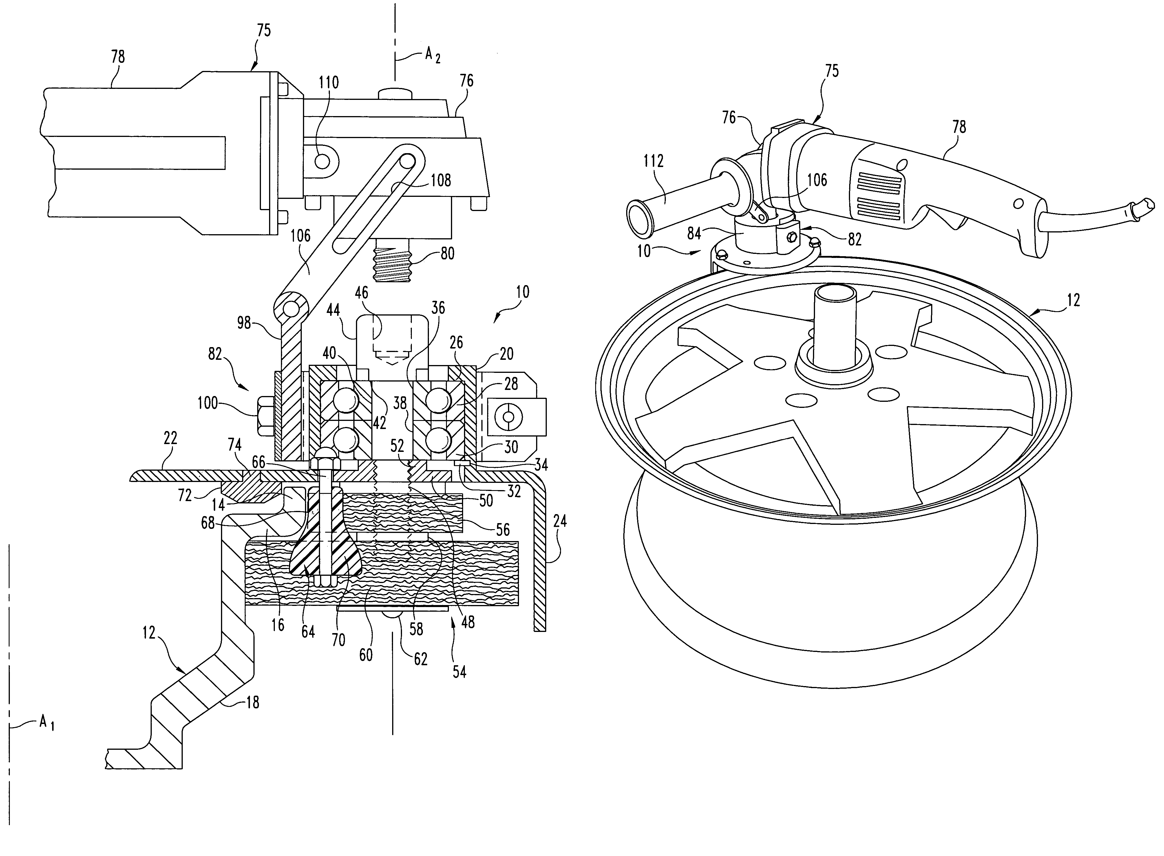
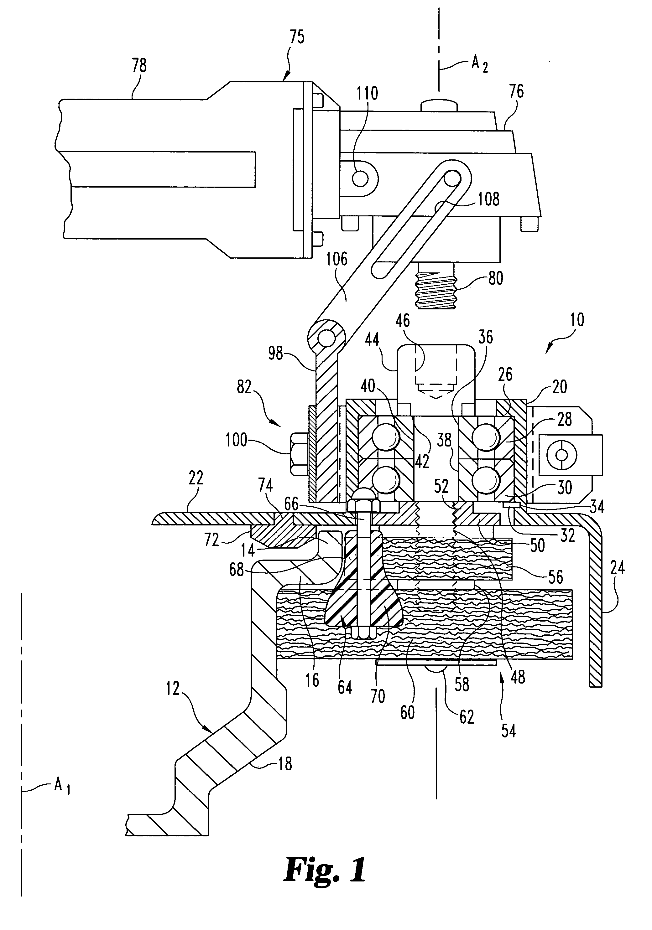
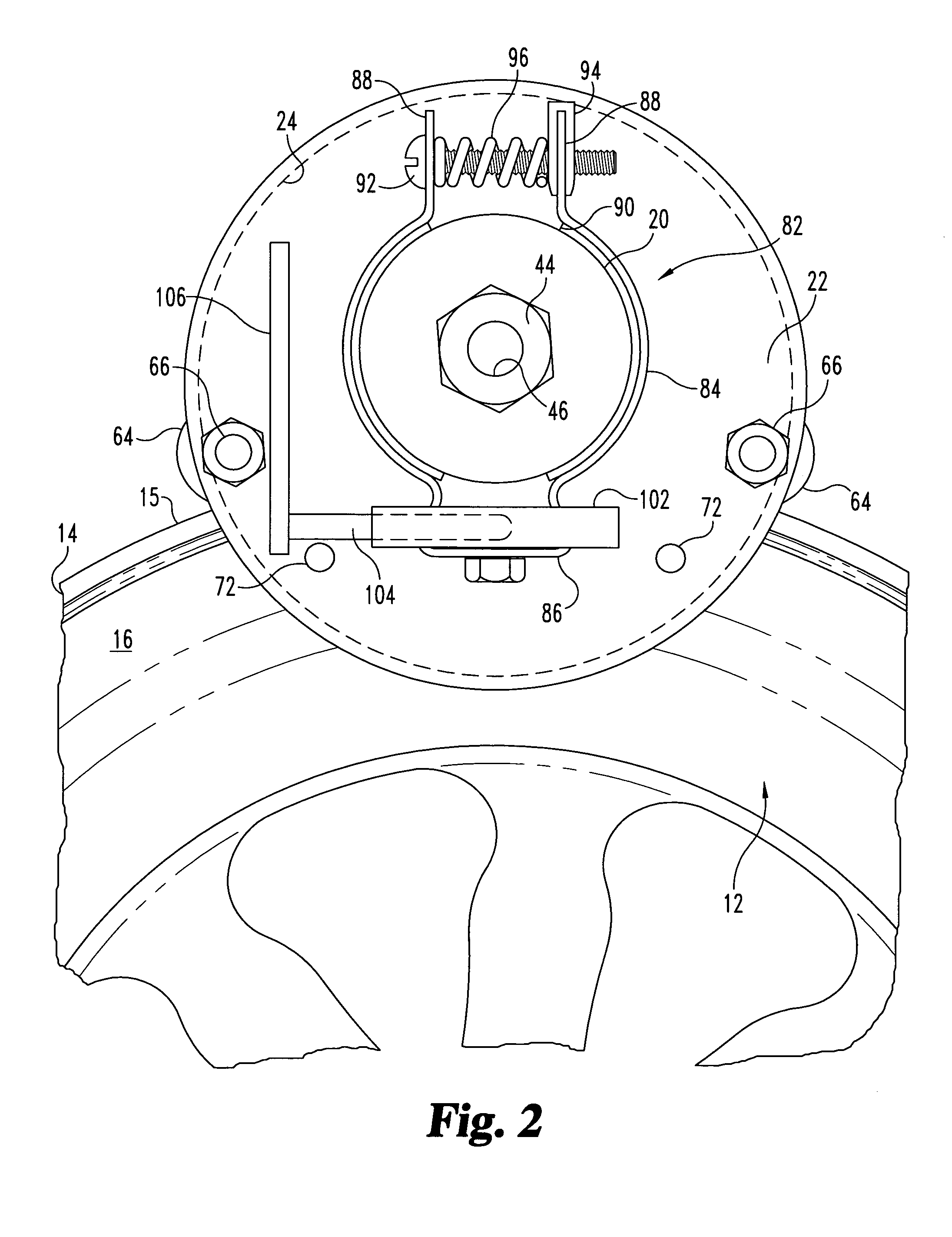
[0010]FIG. 1 and FIG. 2 show a wheel rim cleaning apparatus 10 together with a wheel 12. Wheel 12, in typical fashion, comprises an annular rim 14 having an outside diameter 15 extending parallel to, and concentric with, an axis A1, herein shown not in its true location for illustrative purposes. Rim 14 connects with a radially extending annular section 16, integral with hub section 18 of the wheel 12. As...


PUM


Abstract

Apparatus for cleaning the rim of a wheel. The apparatus comprises a housing journaling a driveshaft, driven by an electric motor and mounting a pair of wire brushes configured to contact the wheel rim. Guides on the housing cause the axis of the drive shaft to be parallel to the wheel axis. In use, the housing pivots to follow the wheel rim while the electric motor remains in the same orientation. A brake mechanism between the housing and electric motor prevents rotation of the housing when the guides are not engaged with the wheel rim.

Description

REFERENCE TO RELATED APPLICATIONS[0001]This application claims the benefit of U.S. Provisional Patent Application Ser. No. 60 / 508,817 filed Oct. 6, 2003, which is hereby incorporated by reference in its entirety.BACKGROUND OF THE INVENTION[0002]The invention relates to a cleaner and, more specifically, a device for cleaning the rims of automotive wheels.[0003]The automotive field has experienced a significant increase in the percentage of wheels made out of cast aluminum or other lightweight alloys. These wheels exhibit increased durability and significantly enhanced appearance. However, these benefits come at a price. The aluminum wheels are significantly more expensive that previous stamped steel wheels and they have a softer surface. This has an impact when tires are being replaced and it is necessary to clean the new tires prior to installing a replacement tire. Very often, the rubber from the replaced tires and / or corrosion accumulates on the rim of the wheel. Most current tire...

Claims


Application Information

Patent Timeline
Patent Type & Authority Patents(United States)
IPC IPC(8): A46B13/02B60S3/06A46B13/00B60S3/04
CPCA46B13/001B60S3/042B60S3/048A46B2200/3046
Inventor PETERS, EUGENE A.
Owner PETERS EUGENE A
Why Eureka
Try Eureka