Apparatus and method for forming alignment layers

a liquid crystal alignment and apparatus technology, applied in the field of apparatus and method for forming liquid crystal alignment layers, can solve the problems of inability to achieve uniform orientation of liquid crystal molecules on the surface of thin films, difficulty in density control, uneven brightness and color of liquid crystal panels, etc., to achieve uniform intensity distribution of ion beams, no uneven brightness and color, and uniform orientation

Inactive Publication Date: 2005-01-06
GLOBALFOUNDRIES INC
View PDF4 Cites 6 Cited by
  • Summary
  • Abstract
  • Description
  • Claims
  • Application Information

AI Technical Summary

Benefits of technology

[0009] An apparatus for forming an alignment layer according to the present invention comprises an ion source for applying ion beams to a thin film on a substrate, and the ion source comprises a grid having a plurality of ion ejection holes of various sizes. The size of the ejection hole varies depending on the ion density. The apparatus of the present invention can ensure a uniform density of ion beams and uniform orientation of liquid crystal molecules.
[0012] The present invention can achieve a uniform intensity distribution of ion beams and uniform orientation of liquid crystal molecules on an alignment layer. Therefore, the present invention makes it possible to produce a liquid crystal display with no unevenness in brightness and color.

Problems solved by technology

If the liquid crystal molecules are not uniformly oriented, a liquid crystal panel suffers from an unevenness of brightness and color.
However, it is apparent from various experiments that the density control is not an easy task.
However, if the intensity distribution of ion beams is not uniform in Y direction shown in FIG. 5(b), uniform orientation of liquid crystal molecules on the surface of the thin film 26 cannot be achieved.

Method used


Image

  • Apparatus and method for forming alignment layers
  • Apparatus and method for forming alignment layers
  • Apparatus and method for forming alignment layers

Examples


Embodiment Construction

[0019] Embodiments of an apparatus and method for forming an alignment layer according to the present invention will be hereinafter described with reference to the accompanying drawings.

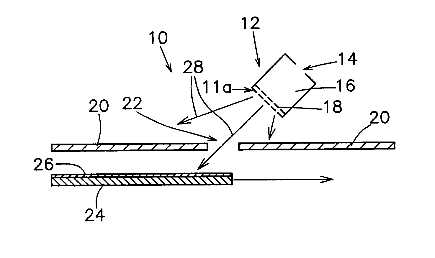
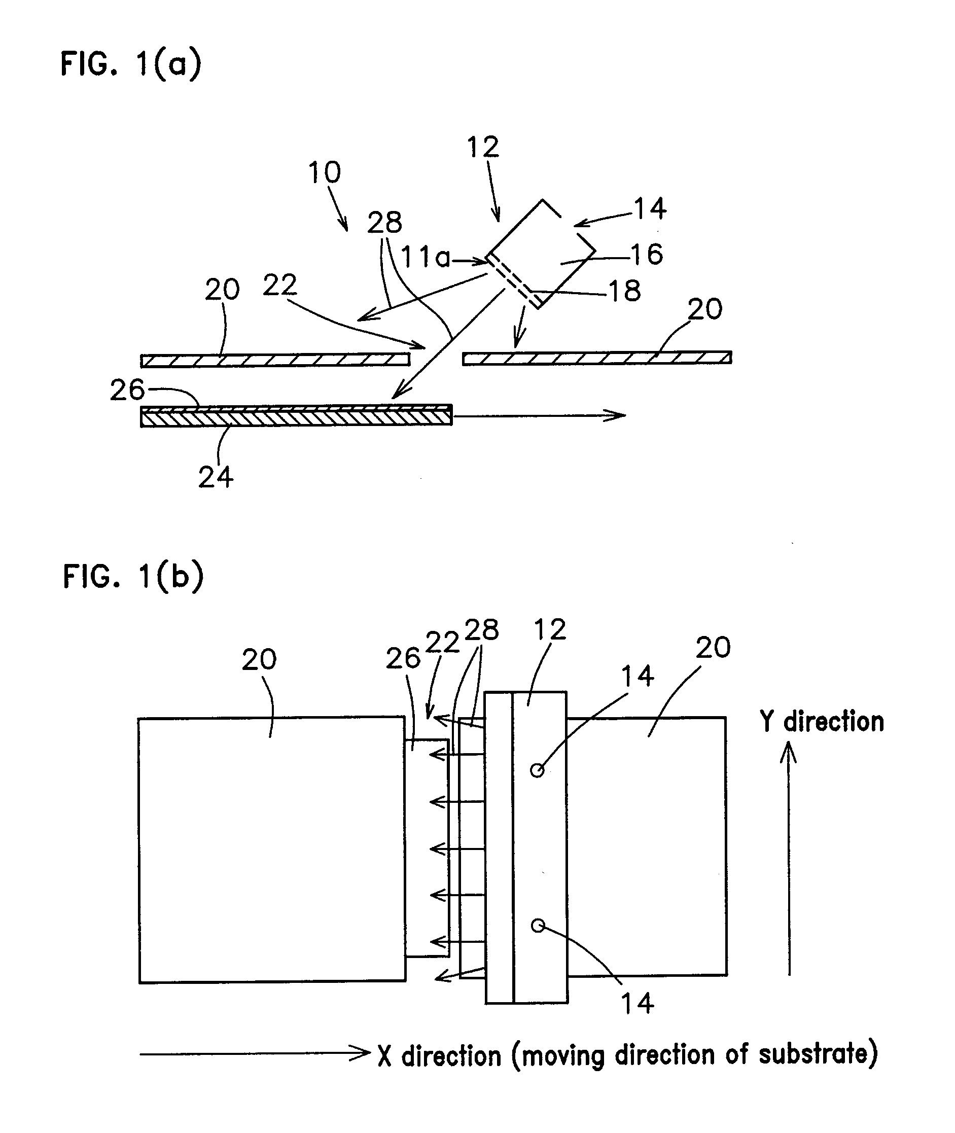
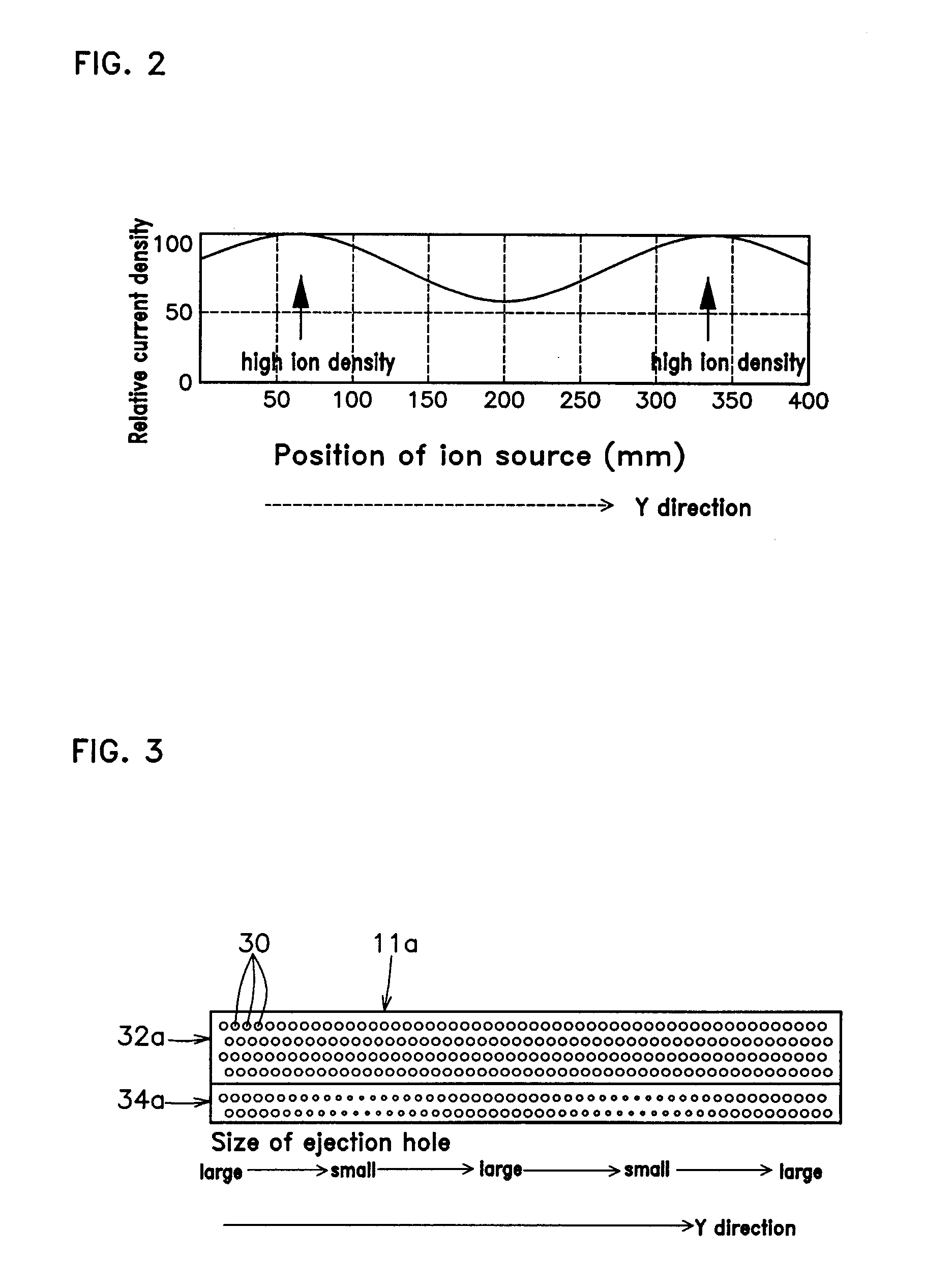
[0020] In an apparatus for forming an alignment layer according to the present invention, a mask 20 is provided between an ion source 12 and a glass substrate 24 with a thin film 26 applied thereon, as shown in FIGS. 1(a) and 1(b). The mask 20 has a slit 22. The apparatus for forming an alignment layer comprises a stage (not shown) for moving the glass substrate 24. A grid 11a of the ion source 12 has a plurality of ion ejection holes 30, as shown in FIG. 3.

[0021] The ion source 12 comprises a plasma generation chamber 16, a gas inlet 14 for introducing gas into the plasma generation chamber 16, an accelerating electrode 18 for accelerating ions generated in the plasma generation chamber 16, and a grid 11a for ejecting the accelerated ions to the outside. The gas is argon (Ar) gas, for example. Whe...


PUM

PropertyMeasurementUnit
diameteraaaaaaaaaa
diameteraaaaaaaaaa
sizesaaaaaaaaaa

Abstract

An object of the present invention is to provide an apparatus and method for ensuring a uniform orientation of liquid crystal molecules of an alignment layer by irradiation with ion beams. An apparatus of the present invention comprises a grid 11a having a plurality of ion ejection holes 30 of various sizes. The size of the ion ejection hole 30 varies depending on an ion density. The size of the ion ejection hole 30 increases with decrease in the ion density.

Description

BACKGROUND OF INVENTION [0001] The present invention relates to an apparatus and method for forming a liquid crystal alignment layer by irradiation with ion beams or atomic beams. [0002] In a liquid crystal display (LCD), an alignment layer is provided so as to orient liquid crystal molecules. It is known that a liquid crystal alignment layer is formed by irradiating a thin film of polyimide or inorganic material with ion beams. By breaking interatomic bonds in the thin film with ion beams, an alignment film is formed. [0003] It is needed that liquid crystal molecules are oriented uniformly all over the alignment layer. If the liquid crystal molecules are not uniformly oriented, a liquid crystal panel suffers from an unevenness of brightness and color. In order to produce an enhanced-definition liquid crystal panel, it is required to ensure much higher degree of uniformity in orientation of liquid crystal molecules than a conventional liquid crystal panel. [0004] In order to achieve...

Claims


Application Information

Patent Timeline
Patent Type & Authority Applications(United States)
IPC IPC(8): G02F1/1337G03C5/00G03F9/00G21G5/00H01J37/08H01J37/302H01J37/317
CPCG02F1/133723G02F1/13378H01J2237/30472H01J37/3023H01J37/08
Inventor OKAZAKI, NOBUOSHIOTA, YASUHIKONAKAGAKI, JOHJI
Owner GLOBALFOUNDRIES INC
Why Eureka
Try Eureka