Starting method for Hall-less single-phase BLDCM

a single-phase, hall-less technology, applied in the direction of motor/generator/converter stopper, electronic commutator, dynamo-electric converter control, etc., can solve the problem of increasing the size of the motor system and manufacturing cost, reducing the ability of the system against the environment variation, and difficult direction control

Inactive Publication Date: 2007-07-10
DELTA ELECTRONICS INC
View PDF2 Cites 8 Cited by
  • Summary
  • Abstract
  • Description
  • Claims
  • Application Information

AI Technical Summary

Problems solved by technology

However, the Hall-effect sensor itself increases the size of the motor system and the manufacturing costs.
Besides, the Hall-effect sensor decreases the capability of the system against the environment variation, e.g., the temperature variation.
But the direction control becomes very difficult when the system is running in sensorless mode, more clearly in Hall-less mode, because the controller cannot determine the rotor's initial position.

Method used


Image

  • Starting method for Hall-less single-phase BLDCM
  • Starting method for Hall-less single-phase BLDCM
  • Starting method for Hall-less single-phase BLDCM

Examples


Embodiment Construction

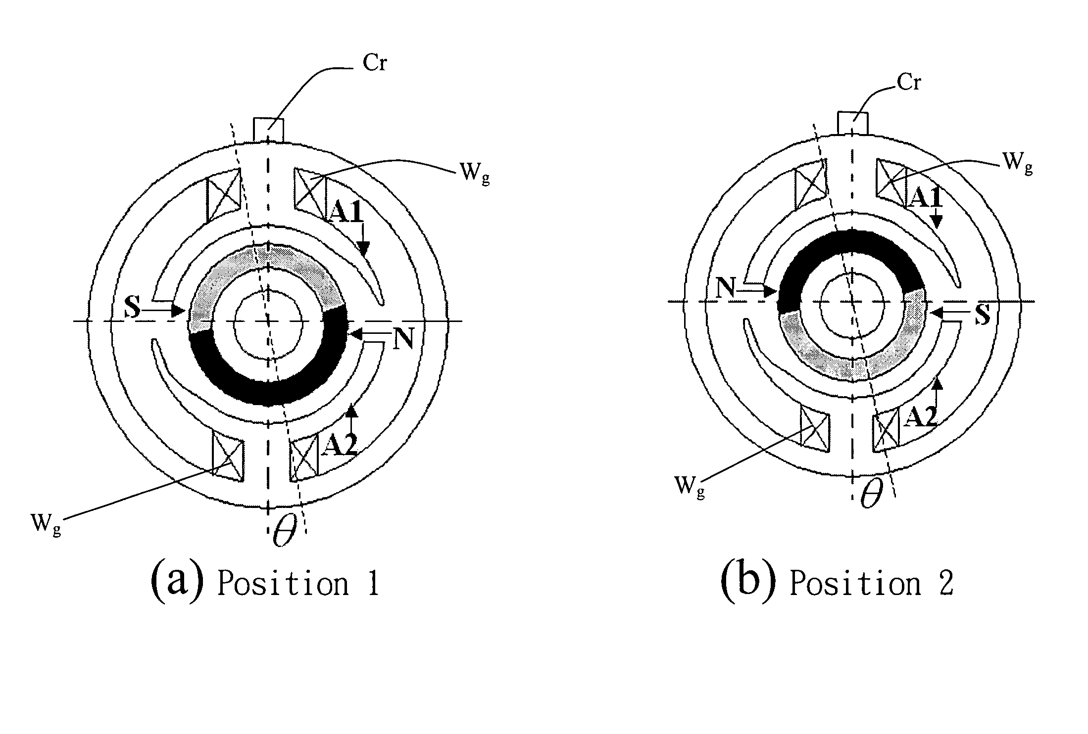
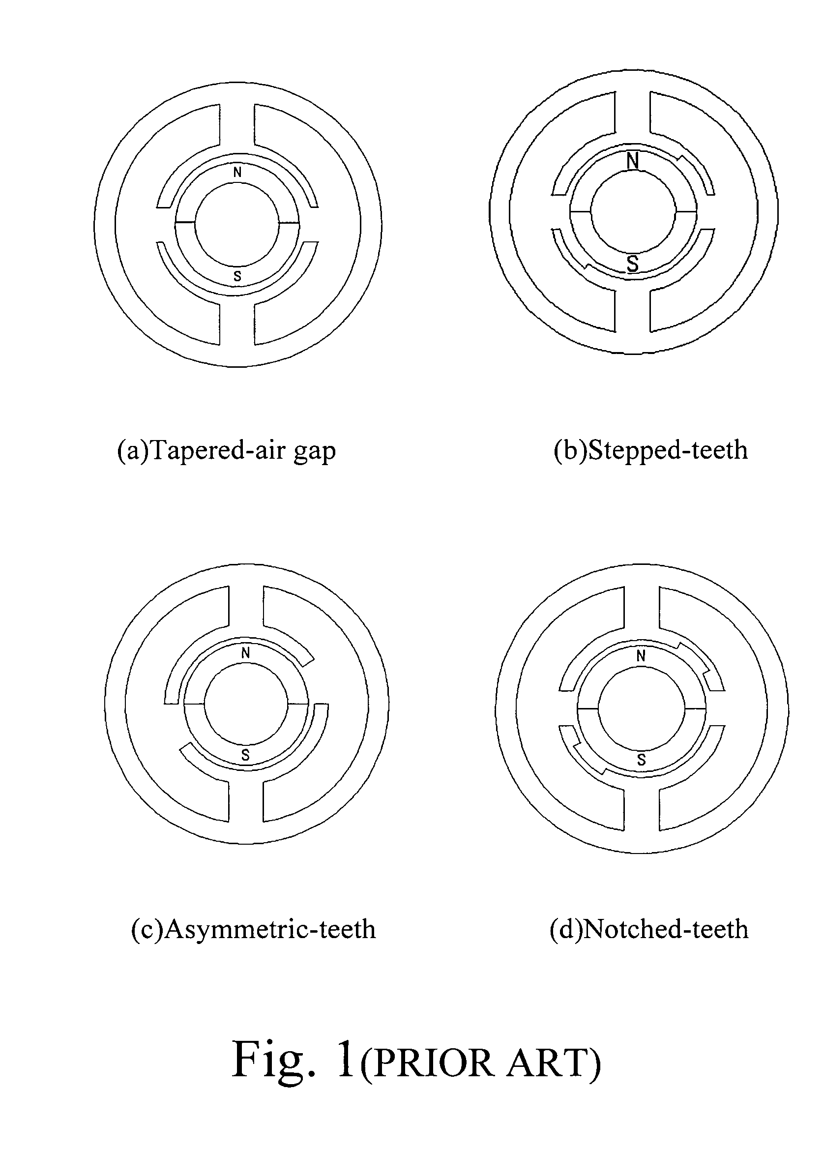
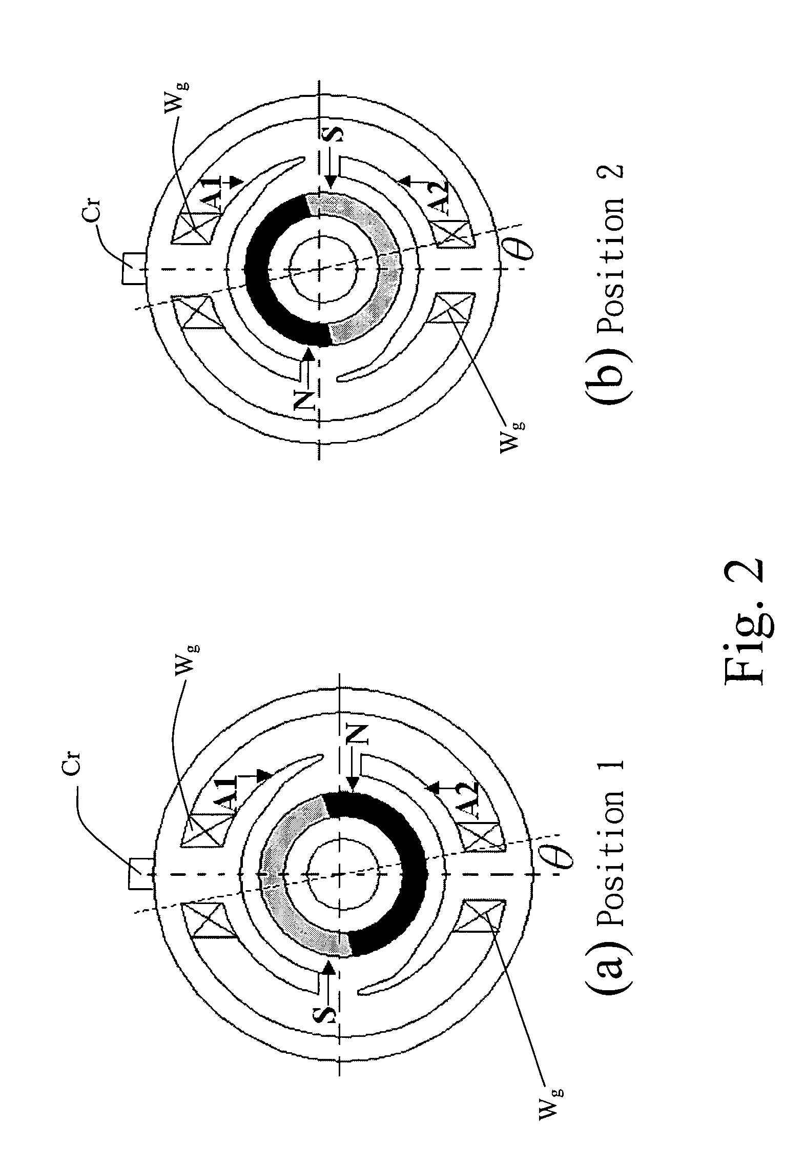
[0036]As mentioned-above, four different structures of the single-phase BLDCM with asymmetrical air gap, the tapered air gap, the stepped-teeth, the asymmetrical-teeth and the notched-teeth as shown in FIGS. 1(a) to 1(d) respectively, can overcome the traditional null-points in motor torque waveform easily. When a single-phase BLDCM having an asymmetrical air gap keeps at standstill, the position of its rotor with respect to its stator has two possibilities, Position 1 and Position 2, as shown in FIGS. 2(a) and 2(b) respectively. That is, the polarity of the rotor pole aligned with the special stator tooth named A1, as shown in FIGS. 2(a) and 2(b), is either south pole labeled as S (as shown in FIG. 2(a)) or north pole labeled as N (as shown in FIG. 2(b)).

[0037]In the present invention, the proposed starting methods are analyzed according to the simplest motor model just with two stator teeth, A1 and A2, and two permanent magnet poles, N and S, as shown in FIGS. 2(a) and 2(b). Surel...


PUM


Abstract

The methods for starting a Hall-less single-phase BLDCM having an asymmetrical air gap are proposed. The provided methods are employed to input a specific amount of current impulse and stop the current impulse at a specific time such that the rotor of the single-phase BLDCM having an asymmetrical air gap can be realized to rotate in the pre-determined direction through one of the cogging torque and the rotor inertia after that specific time so as to accomplish the normal starting of a motor without the Hall-effect sensor.

Description

FIELD OF THE INVENTION[0001]The present invention relates to the control of a single-phase brushless DC motor (BLDCM). More particularly, the present invention relates to the starting method for a Hall-less single-phase BLDCM having an asymmetrical air gap.BACKGROUND OF THE INVENTION[0002]The single-phase BLDCM is widely used in low starting torque and small power fields such as pumps, blowers and cooling fans. The single-phase BLDCM requires a suitable current commutation signal synchronized with the rotor position for proper operation. In most applications, a Hall-effect position sensor is used to detect the rotor position and control the motor. However, the Hall-effect sensor itself increases the size of the motor system and the manufacturing costs. Besides, the Hall-effect sensor decreases the capability of the system against the environment variation, e.g., the temperature variation. Many Hall-less BLDCM drives that detect the rotor position have been introduced.[0003]The singl...

Claims


Application Information

Patent Timeline
Patent Type & Authority Patents(United States)
IPC IPC(8): H02K21/00
CPCH02P6/008H02P6/185H02P6/20H02P6/26
Inventor WANG, WEIZIWU, ZHIGANJIN, WANBINGYING, JIANPINGWU, LIJIANHUANG, SHIH-MINGHUANG, WEN-SHI
Owner DELTA ELECTRONICS INC
Why Eureka
Try Eureka