Method and apparatus for multiphase, fast-locking clock and data recovery

a multi-phase, fastlocking technology, applied in the direction of digital transmission, synchronisation signal speed/phase control, transmission, etc., can solve the problems of transmission clock, low power dissipation, and inability to fast lock, so as to achieve stable tracking, fast locking, and cost-effective implementation

Active Publication Date: 2007-07-10
ALCATEL-LUCENT USA INC +1
View PDF5 Cites 4 Cited by
  • Summary
  • Abstract
  • Description
  • Claims
  • Application Information

AI Technical Summary

Benefits of technology

[0009]We have invented a method and apparatus for clock and data recovery wherein a plurality of clock signals, each having a different phase, is generated. The phase of a received input signal data stream is determined and the generated clock signal in the plurality that corresponds to the phase of the input data stream is selected and used to sample the input signal data stream. This clock and data recovery method allows a) fast locking to a rapidly changed phase of the transmission clock, and b) stable tracking of a slowly changing phase of the transmission clock. Rapid locking of the receive clock to the transmit clock and the subsequent reliable tracking thereof is achieved by utilizing only digital circuits, which also results in cost-effective implementation and reliable operation versus that of analog circuits. Such rapid locking also minimizes the “guard band” between, as well as the time overhead due to clock and data recovery within, consecutive transmission bursts, while stable tracking provides reliable data tracking, resulting in the efficient use of bandwidth. This method and apparatus also allows for infrequent use of the clock locking and tracking circuitry, which is beneficial as it results in low power dissipation.

Problems solved by technology

While the prior methods such as those disclosed in the '290 and '872 patents and the '008 patent application are advantageous in many regards, they are not capable of both fast locking when fast changes to the transmission clock occur and, simultaneously, stable tracking of a slowly changing phase of the transmission clock.
This method and apparatus also allows for infrequent use of the clock locking and tracking circuitry, which is beneficial as it results in low power dissipation.

Method used


Image

  • Method and apparatus for multiphase, fast-locking clock and data recovery
  • Method and apparatus for multiphase, fast-locking clock and data recovery
  • Method and apparatus for multiphase, fast-locking clock and data recovery

Examples


Embodiment Construction

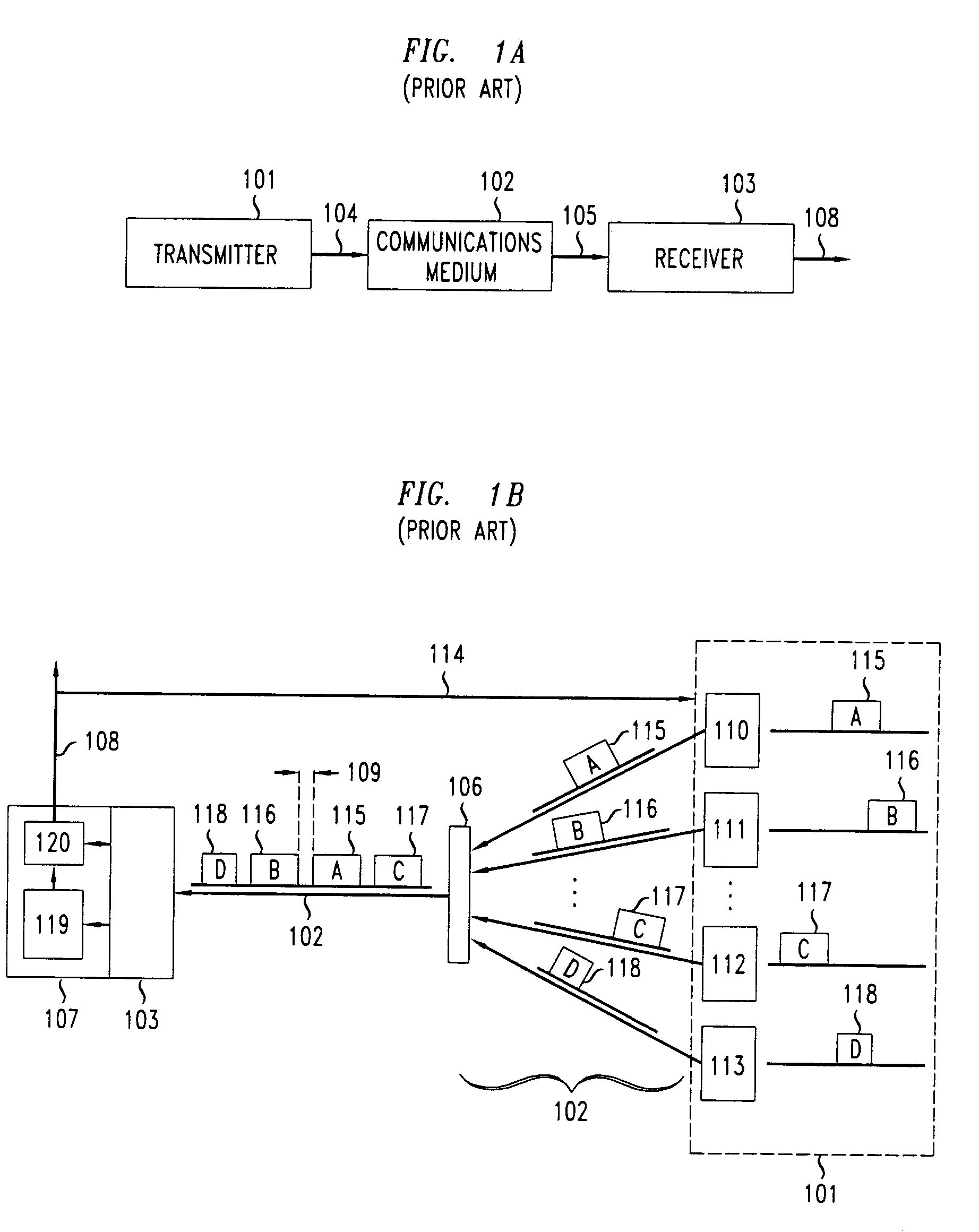
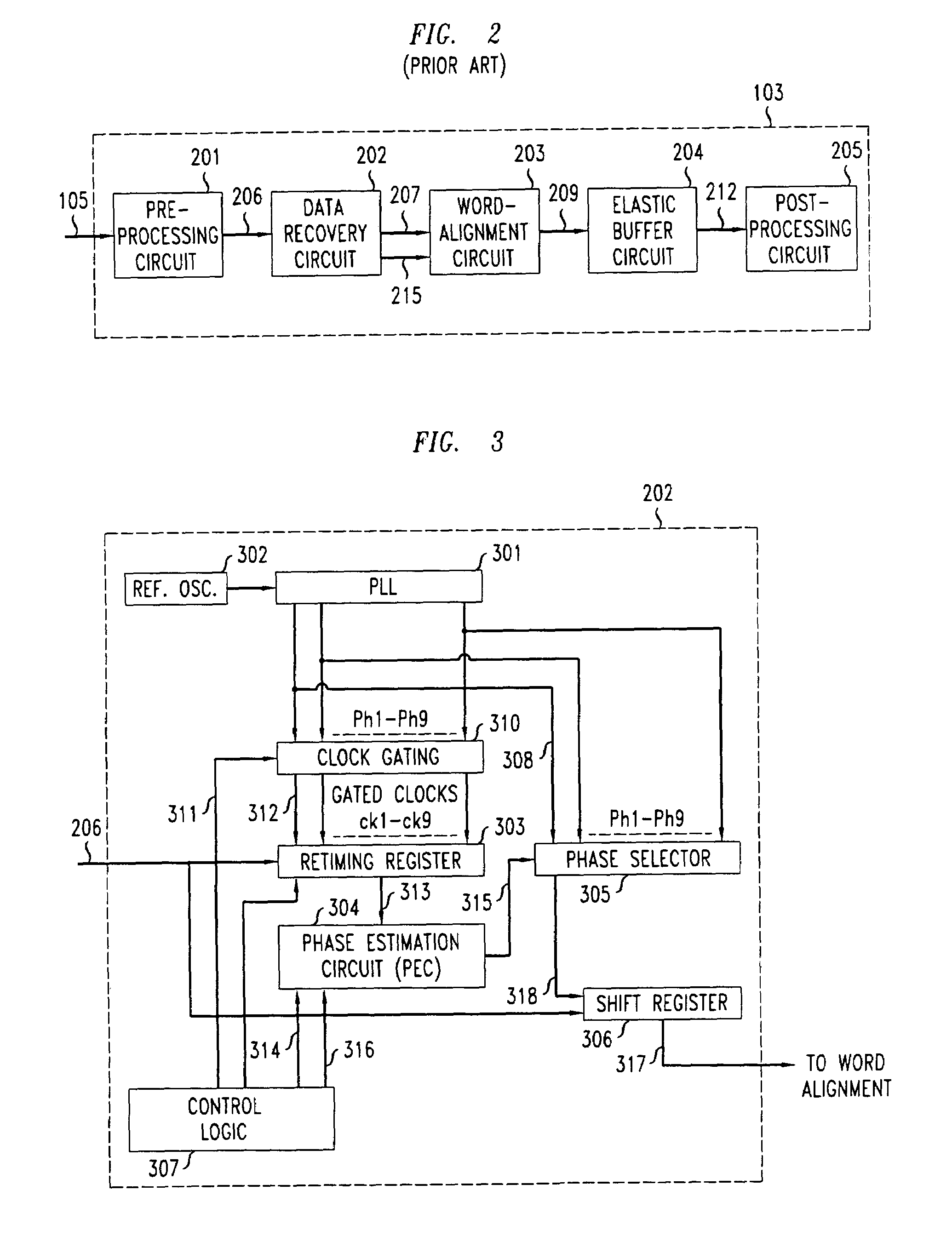
[0019]FIG. 1A shows an illustrative communications network having a transmitter 101, a communication medium 102, and a receiver 103, connected as shown in the FIG. 1. Data stream 104 is outputted by the transmitter 101 into the communication medium 102 and is carried by medium 102 to receiver 103 as input data stream 105. The receiver 103 decodes input data stream 105 to produce output 108, which comprises an output data word stream supplemented with timing information.

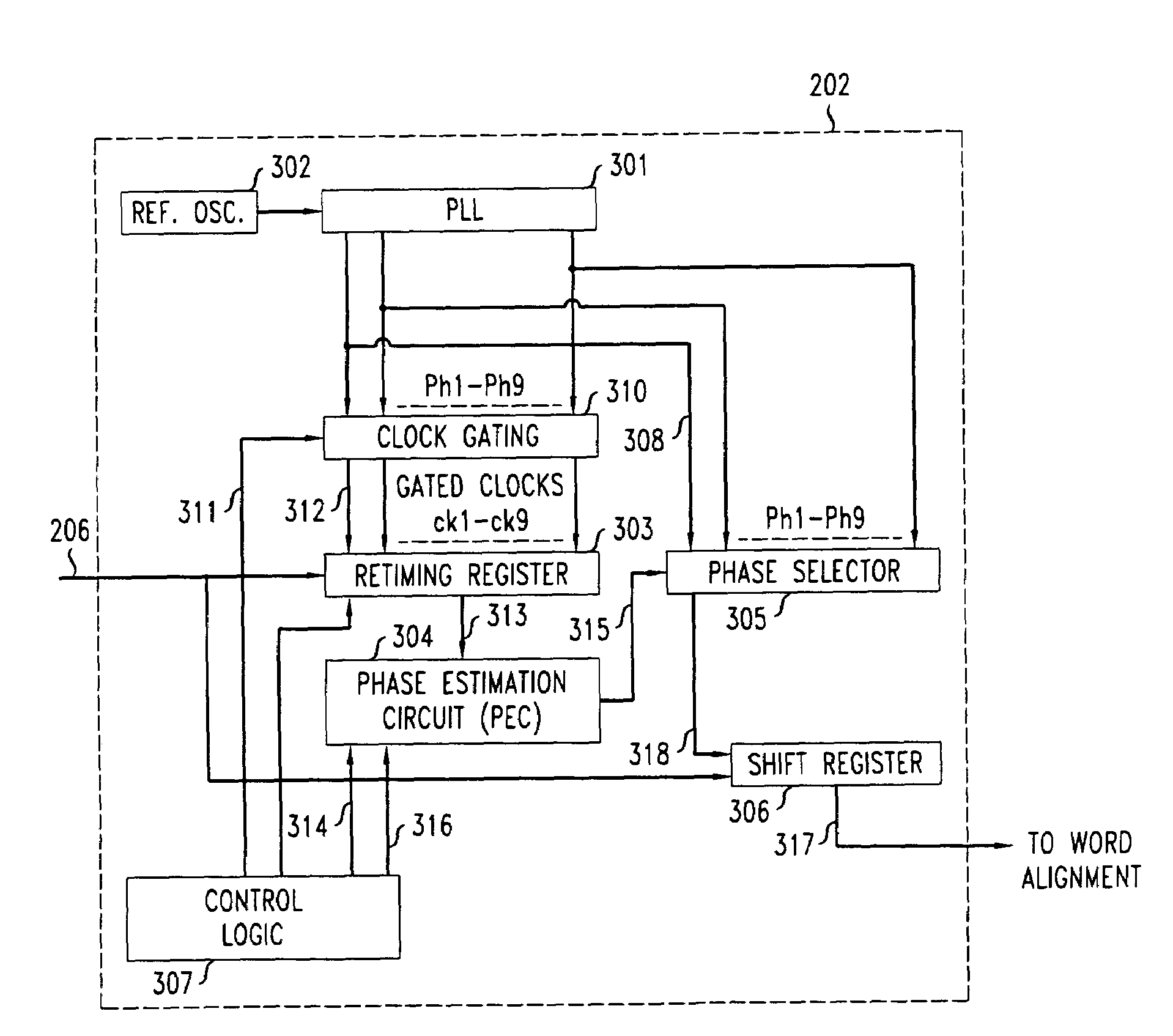
[0020]FIG. 1B shows a more specific illustrative communications network, namely a time-division multiple access (TDMA) passive optical communication network (PON) having multiple user transmitter nodes 110–113, within a group 101 of transmitters, transmitting data and receiving scheduling information from a central office node 107. While a TDMA PON is one representative example, one skilled in the art will recognize that the principles of the present invention may be applied to any network with one or more transmitter...


PUM


Abstract

A method and apparatus for clock and data recovery that is advantageous in burst-mode systems is disclosed. This clock and data recovery method allows a) fast locking to a rapidly changed phase of the transmission clock, and b) stable tracking of a slowly changing phase of the transmission clock. Such fast locking minimizes the “guard band” between consecutive transmission bursts, while stable tracking provides reliable data tracking, resulting in the efficient use of bandwidth. A plurality of clock signals, is generated, each having a different phase. The phase of an input signal data stream is determined and a desired clock signal in the plurality that corresponds to the phase of the input data stream is selected and used to sample the input signal data stream.

Description

FIELD OF THE INVENTION[0001]The invention relates to digital data transmission networks and, more specifically, to enhancing the efficiency of data transmission in digital data transmission networks.BACKGROUND OF THE INVENTION[0002]There are numerous manners in which to transfer data from a transmitter to a receiver. In a typical system for transferring data, a transmitter has clock circuitry that controls the speed at which data is transferred via a communications medium. A receiver in such a system also typically has clock circuitry that controls the speed at which the data that is received from the communications medium is processed.[0003]Ideally, the receiver's clock and the transmitter's clock will operate at exactly the same frequency and will be appropriately aligned in phase. However, the clock used by the transmitter is typically different in phase and slightly different in frequency as compared to that of the receiver. Further, the data may be variably delayed through the ...

Claims


Application Information

Patent Timeline
Patent Type & Authority Patents(United States)
IPC IPC(8): H03D3/24H04L7/033H04L7/04
CPCH04L7/0338H04L7/042
Inventor BOLES, GLENN MDUNLOP, ALFRED EARLMATTHEWS, MANYALIBO JOSEPHSUVAKOVIC, DUSANVAN VEEN, DOUTJE T.
Owner ALCATEL-LUCENT USA INC
Why Eureka
Try Eureka