Door lifting apparatus and method

a technology for lifting apparatuses and doors, applied in the field of apparatus for lifting and transporting automobile doors, can solve the problems of requiring significant installation and maintenance expenditures, cumbersome operation, and high cost of apparatuses, and achieve the effect of lifting and lowering the door

Inactive Publication Date: 2007-07-17
HONDA MOTOR CO LTD
View PDF47 Cites 24 Cited by
  • Summary
  • Abstract
  • Description
  • Claims
  • Application Information

AI Technical Summary

Problems solved by technology

However, these apparatuses can be expensive to purchase and maintain, and can be cumbersome to operate.
While such devices work satisfactorily, they require significant expenditures to install and maintain, and are not readily adaptable to changes in the assembly layout.

Method used


Image

  • Door lifting apparatus and method
  • Door lifting apparatus and method
  • Door lifting apparatus and method

Examples


Embodiment Construction

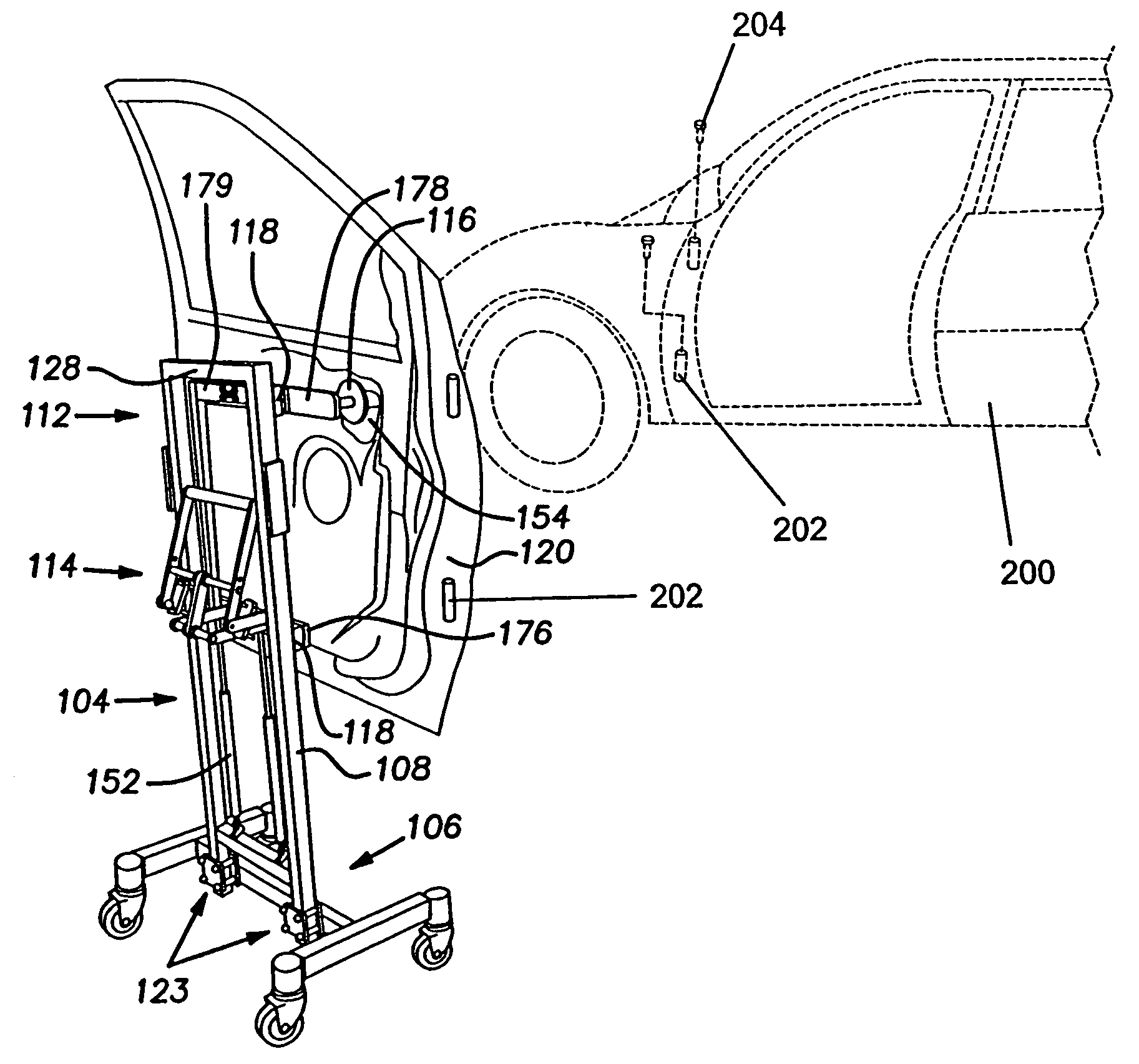
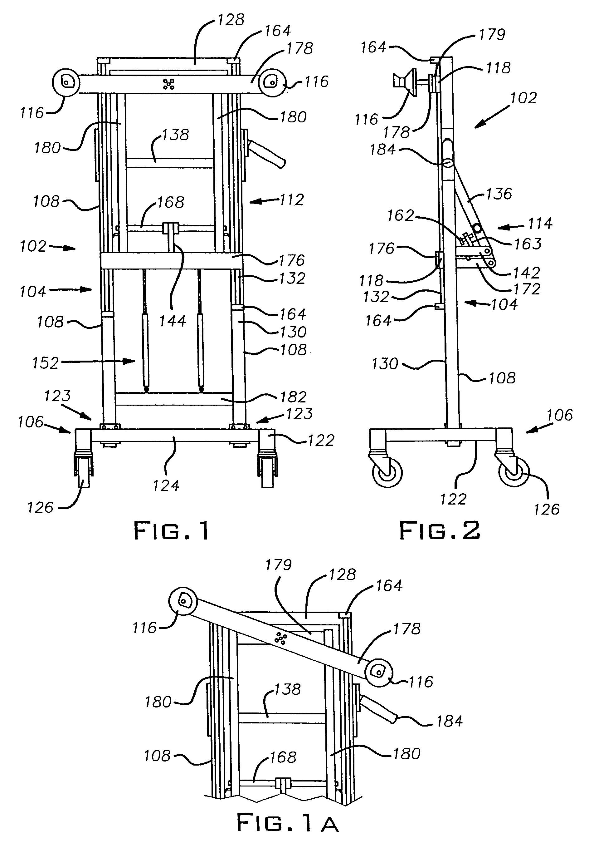
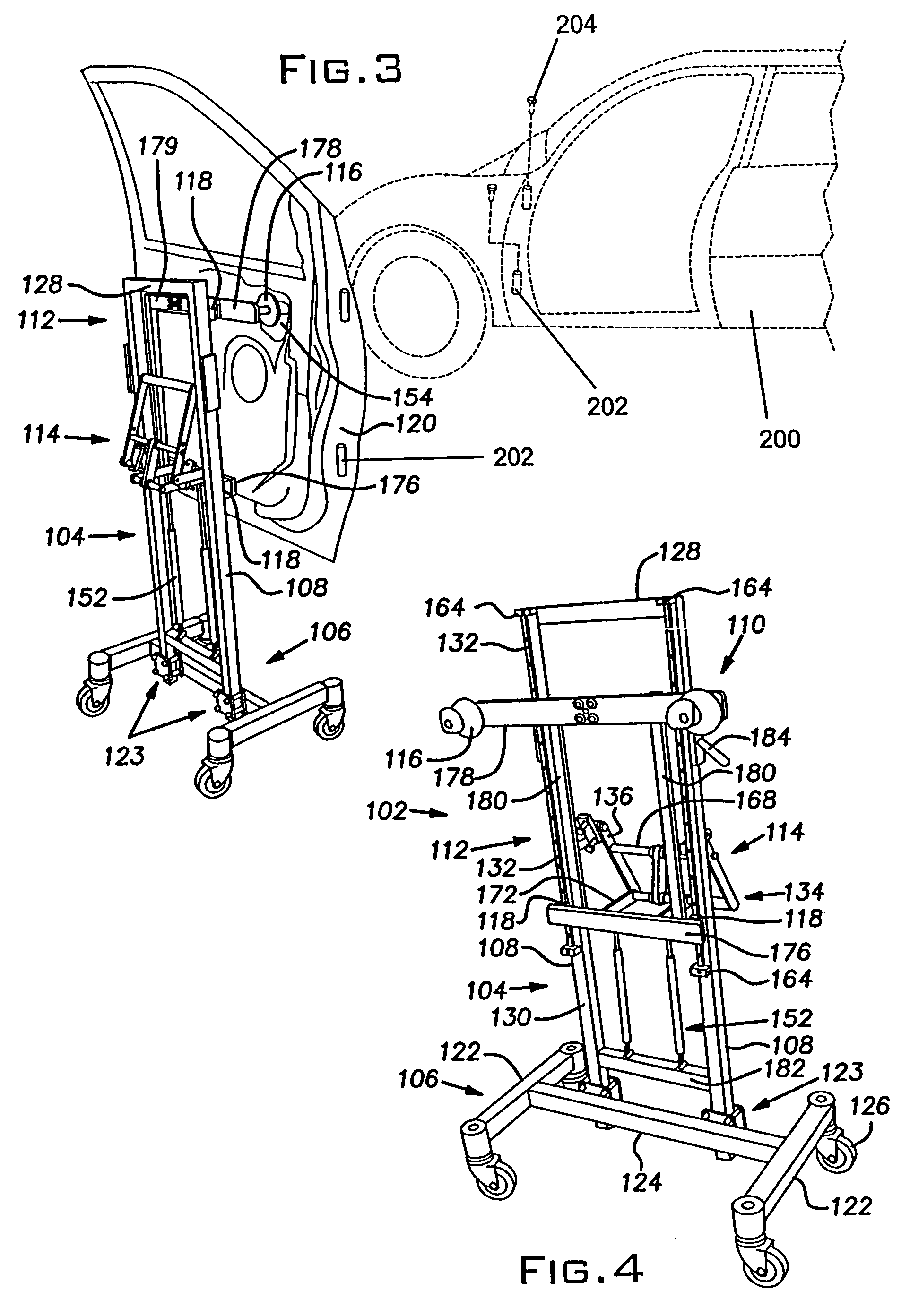
[0019]With reference to the drawing figures, a door lifting and transporting apparatus 102, which is operable to lift and support a vehicle door 120, includes a frame 104 and a lift mechanism 110. The frame includes a base 106, a pair of upright supports 108, an upper support 128, and a lower support 182.

[0020]The base 106 includes a pair of support bars 122 that are interconnected by a cross bar 1.24. Each support bar 122 has a caster or wheel secured to each end thereof. The cross bar 124 is secured to the support bars 122 at location that is offset from the midpoint of the support bars 122, as illustrated.

[0021]A bottom end of each upright support 108 is adjustably secured to the cross bar 124, while a top end of each upright support 108 is rigidly interconnected by the upper support 128. A lower support 182 extends between and rigidly interconnects the upright supports 108 at a location vertically spaced from the base 106, as illustrated. The upper and lower supports 128,182 are...


PUM

PropertyMeasurementUnit
areasaaaaaaaaaa
heightaaaaaaaaaa
lengthaaaaaaaaaa

Abstract

A door lifting apparatus includes a frame and a lift mechanism. The lift mechanism includes a slide and a lever. The slide includes a plurality of holders and a plurality of glides, wherein the holders are operable to engage and support a door while the glides cooperate with rails provided upon the frame to guide the slide along the rails. Pivotal movement of the lever moves the slide vertically relative to the upright supports, thereby raising or lowering the door.

Description

CROSS-REFERENCE TO RELATED APPLICATIONS[0001]This application is a continuation of U.S. patent application Ser. No. 10 / 455,474, filed on Jun. 5, 2003 now U.S. Pat. No. 7,008,166.BACKGROUND OF THE INVENTION[0002]1. Field of the Invention[0003]The present invention generally relates to an apparatus for lifting a door, and more particularly, toward an apparatus for lifting and transporting an automobile door.[0004]2. Description of Related Art[0005]During the manufacture of a vehicle, it may be necessary to remove a vehicle door and transport the door to another location for subsequent assembly before reattaching the door to the vehicle. As vehicle doors are usually heavy, apparatuses that can assist in the lifting and transport of vehicle doors are often employed for this task. Several apparatuses are currently used for such purposes. However, these apparatuses can be expensive to purchase and maintain, and can be cumbersome to operate.[0006]One such apparatus employs a pneumatic assi...

Claims


Application Information

Patent Timeline
Patent Type & Authority Patents(United States)
IPC IPC(8): B60P1/00
CPCB66C23/48Y10T29/53961Y10S269/905
Inventor GRIMES, MARK
Owner HONDA MOTOR CO LTD
Why Eureka
Try Eureka