
Venting devices for surgical casts and other orthopedic devices

a technology of surgical casts and ventilation devices, which is applied in the field of surgical cast ventilation devices and medical devices, can solve the problems that devices have not met with commercial success to da

Active Publication Date: 2007-07-31
BARBERIO ALESSANDRO
View PDF43 Cites 20 Cited by
  • Summary
  • Abstract
  • Description
  • Claims
  • Application Information

AI Technical Summary

Benefits of technology

"The invention is a venting device for use under a surgical cast or other orthopedic device. It includes two elongate strips of flexible material, one of which is porous. These strips are spaced apart from each other and extend parallel to each other. Flexible, solid spacer members are arranged between the two strips and connect them together. The venting device also has a moisture-absorbent, porous fabric layer that covers the outer side of the porous strip and at least partially covers the opposite side edges of the venting device. The porous strip has numerous holes distributed evenly over its outer side. The invention also includes a venting apparatus that includes a flexible tube material with at least some elasticity, which has a central axis and two opposite ends. The venting devices are attached to the inner surface of the tube and each is arranged in a side edge to side edge manner relative to adjacent venting devices. The porous strip of each venting device faces radially inwardly. The flexible tube can be made of SURGILAST® net. The technical effects of the invention include improved air circulation, reduced swelling, and reduced discomfort for patients wearing orthopedic devices."

Problems solved by technology

A variety of devices for venting surgical casts have been proposed in the past but generally speaking these devices have not met with commercial success to date.

Method used


Image

  • Venting devices for surgical casts and other orthopedic devices
  • Venting devices for surgical casts and other orthopedic devices
  • Venting devices for surgical casts and other orthopedic devices

Examples


Embodiment Construction

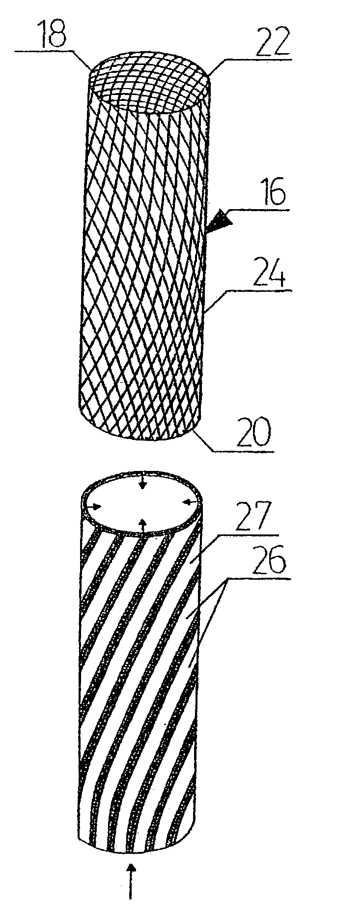
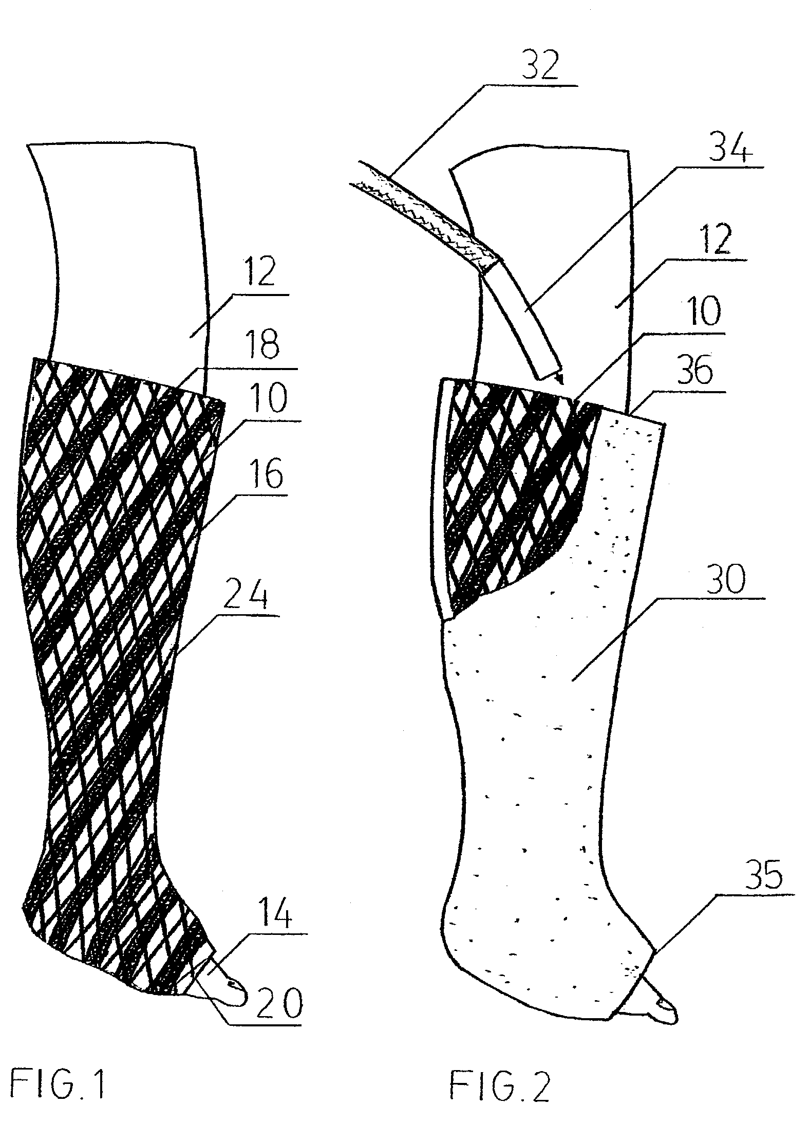
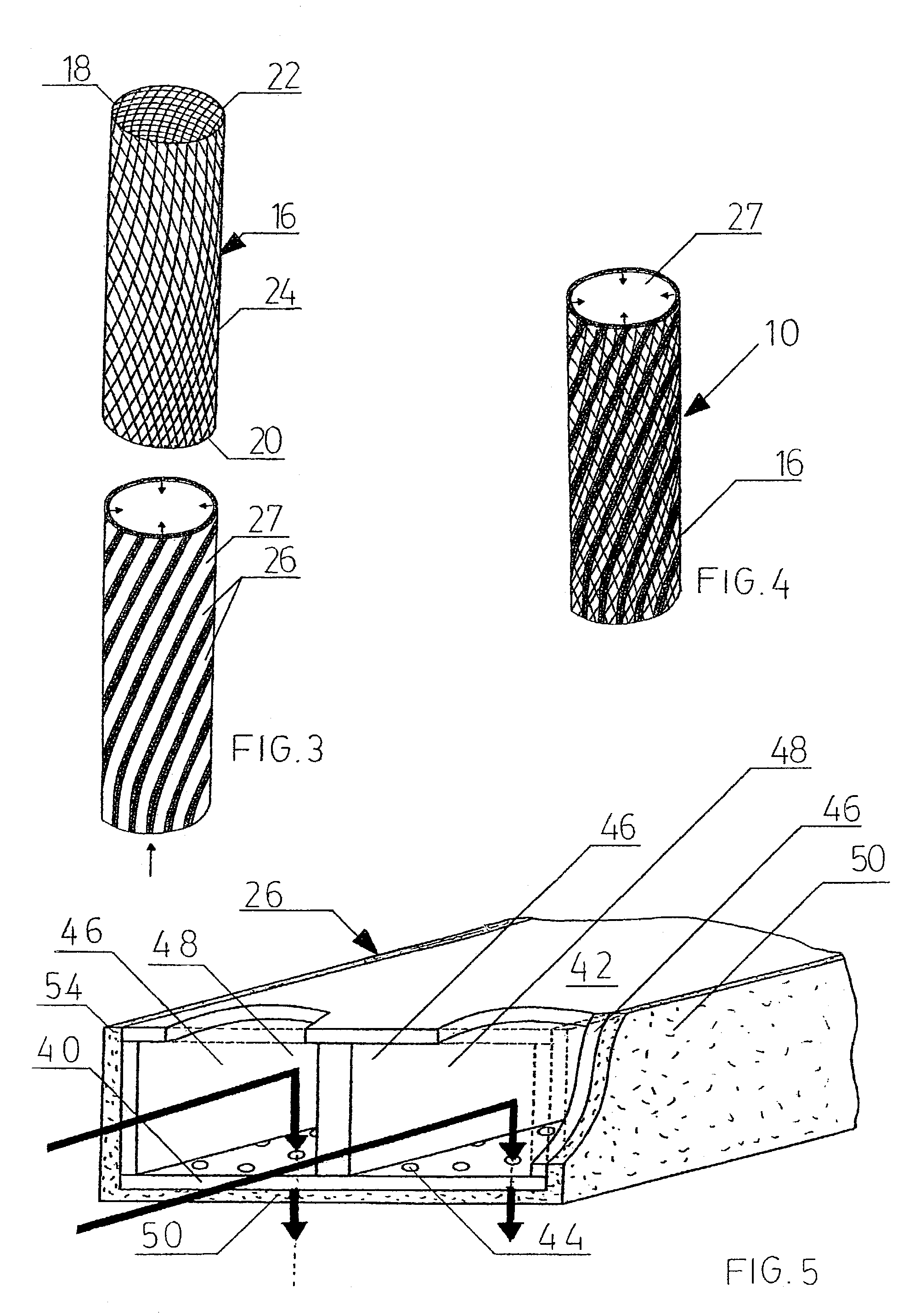
[0039]Illustrated in FIG. 1 is one version of a venting apparatus 10 constructed in accordance with the invention. The apparatus 10 is shown applied around the lower section of a human leg 12 and a foot 14. The preferred apparatus includes a porous, flexible tube 16 of material having at least some elasticity and preferably in the form of a net structure. This tube can be seen most clearly in FIG. 3 where it is shown separately from the remainder of the venting apparatus. The tube has two opposite ends 18 and 20 which are open and inner and outer surfaces 22 and 24. The tube in one preferred embodiment comprises a SURGILAST® net which is a stretchable piece of fabric material having a significant amount of elasticity which allows the venting apparatus to be slid over the desired body part, i.e., a body part with a broken bone that must be kept immobile by means of a cast. This tube can preferably be adjusted in its diameter by twisting its end sections in opposite directions about i...


PUM


Abstract

A surgical cast venting device comprises two elongate strips or two layers of flexible material, at least one of which is porous. The strips or layers are spaced apart from each other and extend parallel to each other. Flexible, solid spacer members are arranged between the two strips or layers and connect them together. These members form air passageways between adjacent spacers so that air is normally free to pass along the passageways. A moisture-absorbent fabric layer extends along an outer side of the porous strip or layer opposite the spacers. In an alternate version, there is a first strip which is porous and a series of substantially flat, flexible outer members arranged in a row from one end of the strip to an opposite end. The outer members are spaced from the strip and opposite side edges of the strip and of the outer members are aligned with one another.

Description

BACKGROUND OF THE INVENTION[0001]This invention relates to venting devices for surgical casts and medical devices such as braces and splints and, in particular, to devices for circulating air under a rigid cast, brace, or splint that may be applied, for example, to permit healing of a broken bone.[0002]A variety of devices for venting surgical casts have been proposed in the past but generally speaking these devices have not met with commercial success to date. Generally, these devices may have tubes which form air passageways to permit air circulation between the rigid cast exterior and the patient's skin. One such venting device is taught in recent U.S. Pat. No. 4,898,160 which issued Feb. 6, 1990 to Alliance Group Inc. This device includes a multiple channeled, flexible form that is placed adjacent to the skin and that is able to adapt to the contour of the body part. The sloping walls of the channels can be formed with a plurality of spaced-apart apertures. Extending upwardly fr...

Claims


Application Information

Patent Timeline
Patent Type & Authority Patents(United States)
IPC IPC(8): A61F5/00A61F5/01A61F5/058A61F13/04
CPCA61F13/041
Inventor BARBERIO, ALESSANDRO
Owner BARBERIO ALESSANDRO
Learn More