Cement control ring

Inactive Publication Date: 2007-08-14
BAKER HUGHES INC
View PDF18 Cites 24 Cited by
  • Summary
  • Abstract
  • Description
  • Claims
  • Application Information

AI Technical Summary

Benefits of technology

[0007]A sealing system for a flow tube to keep cement from getting around it to the flapper when the safety valve is in the open position is disclosed. Seals are provided at opposed ends of the flow tube so that the power spring and the flapper will not get fouled with cement pumped through the flow tube in wells that are completed through a production string with the safety valve in place. The seals may be mounted to the flow tube or the surrounding body. A unique seal construction is also disclosed. The force acting on the flow tube to hold the valve open also helps to apply a force against the lower seal adjacent the flapper.

Problems solved by technology

The new issue confronting safety valve manufacturers in dealing with this type of application is how to maintain the integrity of the flapper mechanism during the cementing process.

Method used


Image

  • Cement control ring
  • Cement control ring
  • Cement control ring

Examples


Embodiment Construction

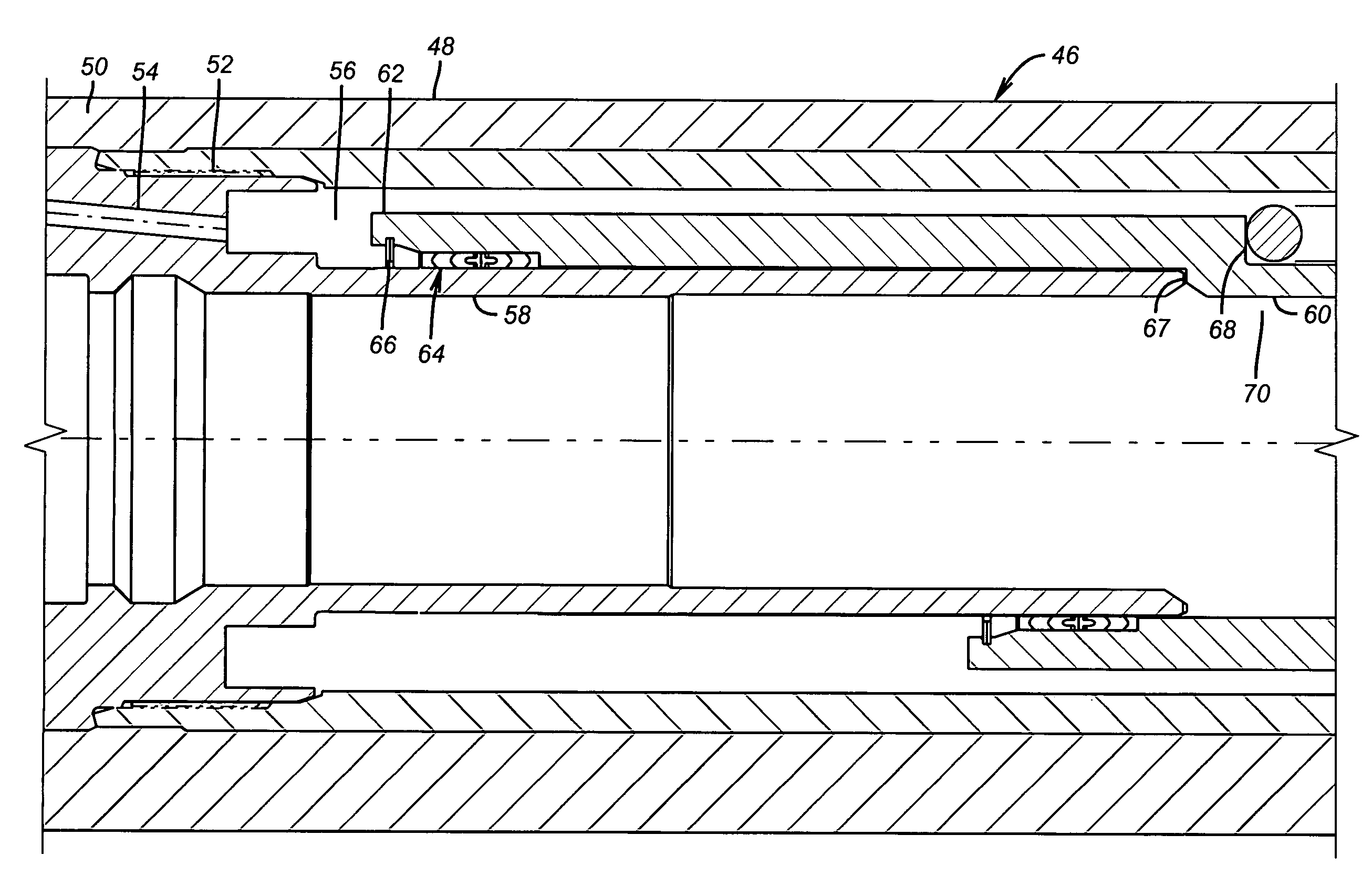
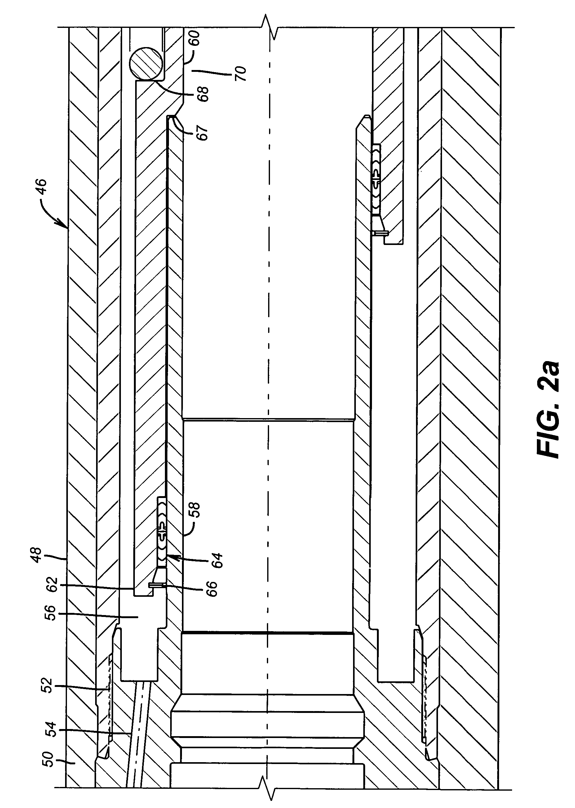
[0010]Referring to FIG. 1a the body 46 has a female component 48 secured to male component 50 at thread 52. Passage 54 has a control line from the surface (not shown) connected to it for selectively pressurizing the chamber 56. Male component 50 has a thin wall 58 to define, in part the cavity 56 and to selectively penetrate into it, when necessary, for a backup mode of operation without using passage 54.However, the preferred access point into cavity 56 is through the flow tube 60 and into annular recess 61, see FIG. 2c. After that a wireline insert valve can be inserted and operated from passage 54. Flow tube 60 has an upper end 62. It retains a seal assembly 64 with a snap ring 66. The flow tube 60 has a shoulder 68 against which the power spring 70 engages. Body 46 has a sub 72, see FIG. 2c, connected at threads 74 to support the ring 76 against which bears the lower end 78 of power spring 70. Lower seal assembly 80 seals between sub 72 and the flow tube 60. Accordingly between ...


PUM


Abstract

A sealing system for a flow tube keeps cement from getting around it to the flapper when the safety valve is in the open position. Seals are provided at opposed ends of the flow tube so that the power spring and the flapper will not get fouled with cement pumped through the flow tube in wells that are completed through a production string with the safety valve in place. The seals may be mounted to the flow tube or the surrounding body. A unique seal construction separates cement from the flapper behind the flow tube. The force acting on the flow tube to hold the valve open also helps to apply a force against the lower seal adjacent the flapper.

Description

PRIORITY INFORMATION[0001]This application claims the benefit of U.S. Provisional Application No. 60 / 487,736 filed on Jul. 16, 2003.FIELD OF THE INVENTION[0002]The field of the invention is subsurface safety valves and more particularly those used in well completion procedures where cement or similar material is pumped through the flow tube that operates the flapper.BACKGROUND OF THE INVENTION[0003]A subsurface safety valve (“safety valve”) is typically installed in well tubing. Normally, the well is drilled and cased. The casing is cemented and the formation is perforated through the casing. A production string, having a packer is run in and the well is put into production through the tubing. The safety valve is in the production string and is normally operated from the surface through one or more control lines that are run in the annular space between the tubing and the casing and above the packer. The pressure applied to the control line drives a piston against an operating sprin...

Claims


Application Information

Patent Timeline
Patent Type & Authority Patents(United States)
IPC IPC(8): E21B34/14E21B34/10
CPCE21B34/102
Inventor THOMPSON, GRANT R.
Owner BAKER HUGHES INC
Why Eureka
Try Eureka