
Portable collapsible stand

a collapsible, portable technology, applied in the field of collapsible stands, can solve the problems of increasing awkwardness, increasing awkwardness, and the tendency to tip

Inactive Publication Date: 2007-08-14
MK DIAMOND PROD
View PDF25 Cites 59 Cited by
  • Summary
  • Abstract
  • Description
  • Claims
  • Application Information

AI Technical Summary

Benefits of technology

"The patent describes a portable collapsible stand that can be easily moved and set up to support a tool. The stand has a first, second, and third support frame that can be connected together, and a telescoping strut that can be extended to support a partially planar surface. The stand can be collapsed and extended to support a tool in a perpendicular position. The stand also has wheels for easy movement and can be set up on a supporting surface. The technical effect of the invention is a portable stand that is easy to move, set up, and support a tool in a safe and stable manner."

Problems solved by technology

Generally, the heavier a tool is, the more awkward it is to transport not only to and from, but also, around project sites.
Because of the high center of gravity, such positioning increases awkwardness and the tendency to tip over while transporting and handling the tool.
Moving such a tool leads not only to increased safety concerns for the tool operator, but also to a likely decrease in work quality.
A tool-stand combination with a high center of gravity is not only less stable, but also more difficult to set up and break down.
Existing conventional portable collapsible stands suffer from the foregoing shortcomings in that they are generally not easily transportable and do not provide a stable surface for the tool they are to support.
Existing devices are also generally not easily set up for operation or broken down for transport or storage.

Method used


Image

  • Portable collapsible stand
  • Portable collapsible stand
  • Portable collapsible stand

Examples


Embodiment Construction

)

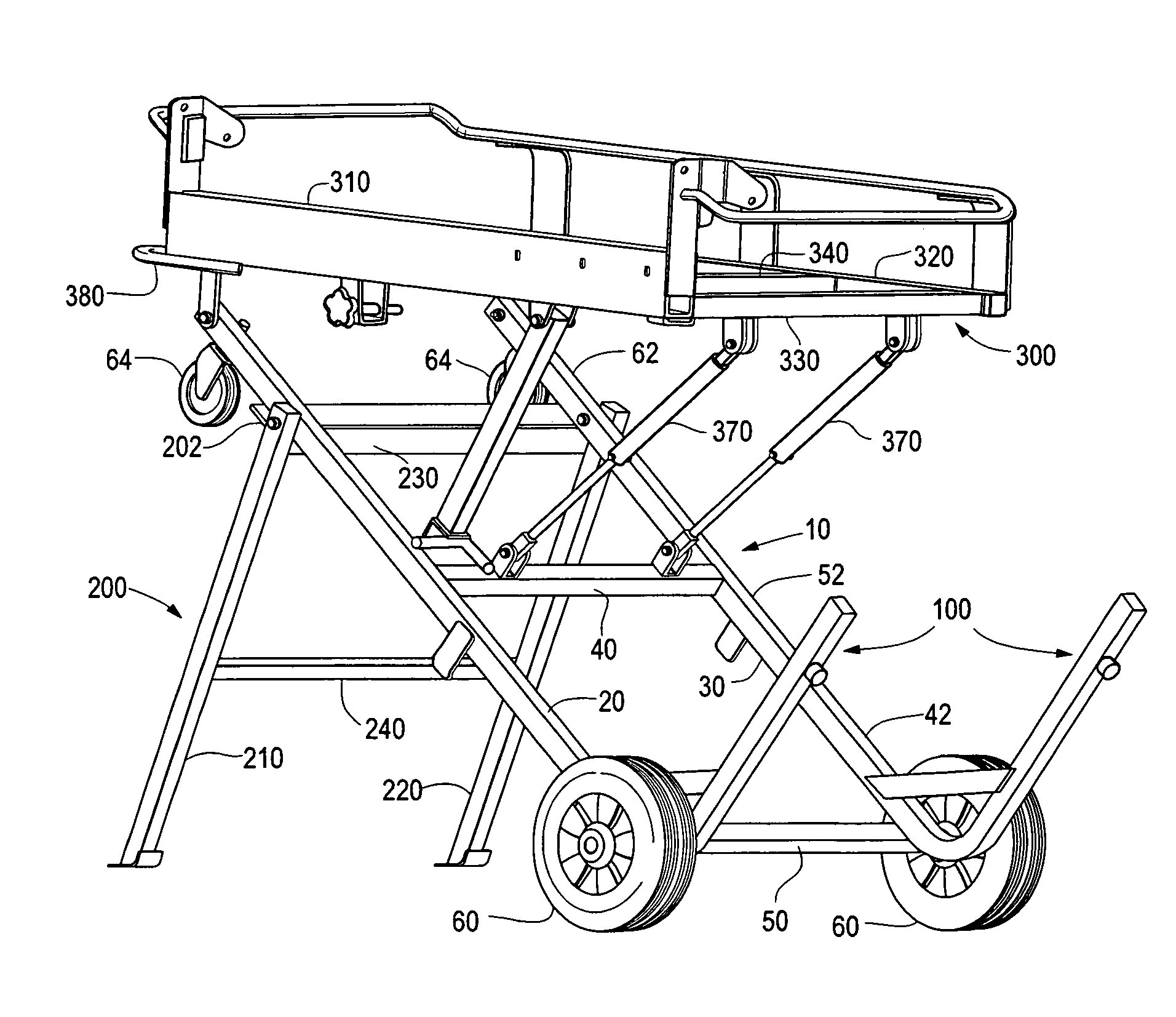
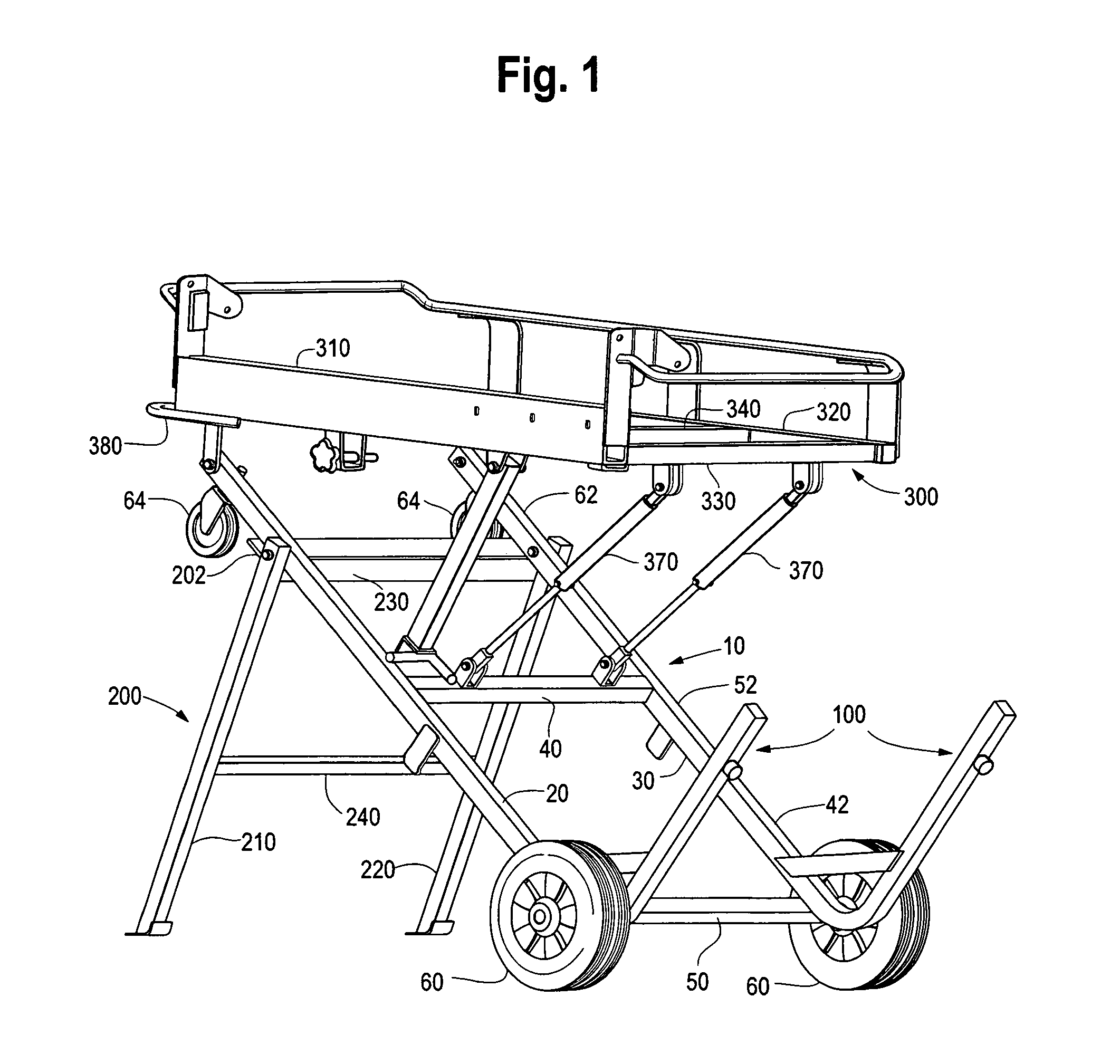
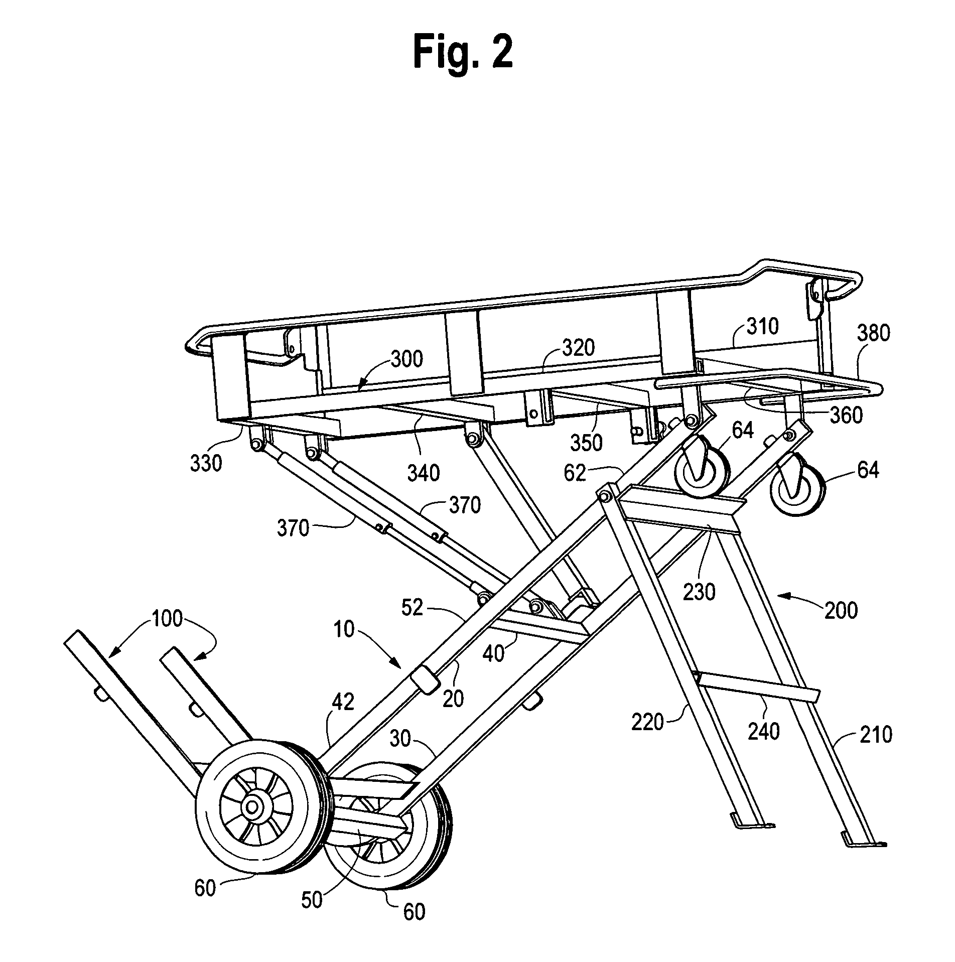
[0032]FIG. 1 is a front isometric view of one embodiment of the present portable collapsible stand in an operating position. FIG. 2 is a side perspective view of the present stand, also in an operating position. The stand comprises several frames connected together where each frame generally defines a planar surface. The frames can be constructed of materials that provide a generally rigid structure such as metal, wood, and / or plastic.

[0033]A first support frame 10 can include two long, straight side members 20, 30 spaced in parallel relation to each other. The side members 20, 30 can be spaced apart by a plurality of cross-members 40, 50 that are of a substantially equal length. The first support frame 10 can be the primary support frame of the stand to which the remaining frames connect.

[0034]The first support frame 10 can be divided into a lower portion 42, a middle portion 52, and an upper portion 62. A second support frame 100 can project generally perpendicular from a lower p...


PUM


Abstract

A portable collapsible stand includes first, second, and third support frames, a work surface frame, and a telescoping strut pivotably connected to the first and work surface frames. The second frame projects perpendicularly from a lower portion of the first frame. A first end of the third frame is rotatably connected to an upper portion of the first frame such that the third frame pivots from a first parallel position to a second perpendicular position with respect to the first frame. An upper portion of the work surface frame is rotatably connected to the upper portion of the first frame. In operation, the stand can assume a collapsed position in which the first, third and work surface frames are generally parallel, and an operating position in which the third frame and first frame are perpendicular and the work surface frame and surface supporting the stand are parallel.

Description

FIELD OF THE INVENTION[0001]The present invention relates to a collapsible stand. More particularly, the present invention relates to a collapsible stand that is portable and provides support for an object, such as a tool. Although the present apparatus is useful for supporting and moving tools, such as a saw, the apparatus could be employed for many types of equipment or needs where portability is desired along with a stable work surface.BACKGROUND OF THE INVENTION[0002]Portable collapsible stands have many uses such as providing portable work surfaces, supporting tools, minimizing storage space requirements, and increasing the mobility of objects that are difficult to move. Such stands are particularly useful in the construction industry where portability of tools is desirable, often leading to increases in work efficiency and ultimate cost savings. Generally, the heavier a tool is, the more awkward it is to transport not only to and from, but also, around project sites.[0003]Wher...

Claims


Application Information

Patent Timeline
Patent Type & Authority Patents(United States)
IPC IPC(8): B60N2/28
CPCB25H1/04
Inventor CHISHOLM, JOHNTSUNG, SHAWNCARROLO, PAULO
Owner MK DIAMOND PROD
Learn More