Skirt for top of rail applicator

a technology for applicators and skirts, which is applied in the direction of rail lubrication, rail wetting/lubrication, rail components, etc., can solve the problems of wasting excess friction modifying materials, modifying material does not work, and substantial amounts of friction modifying materials are wasted

Inactive Publication Date: 2007-08-21
PORTEC RAIL PRODS
View PDF16 Cites 13 Cited by
  • Summary
  • Abstract
  • Description
  • Claims
  • Application Information

AI Technical Summary

Benefits of technology

[0006]The present invention provides for a skirt for use on an applicator bar. The applicator bar includes a body and a flow passageway having an exit end defined in the body. The skirt having a first section and a second section includes a lip defined on the second section of the skirt, wherein the second section is adapted to coact with the body so that the second section is positioned...

Problems solved by technology

Oftentimes, the friction modifying material does not reach the center of the rail or substantial amounts of friction modifying material are wast...

Method used


Image

  • Skirt for top of rail applicator
  • Skirt for top of rail applicator
  • Skirt for top of rail applicator

Examples


first embodiment

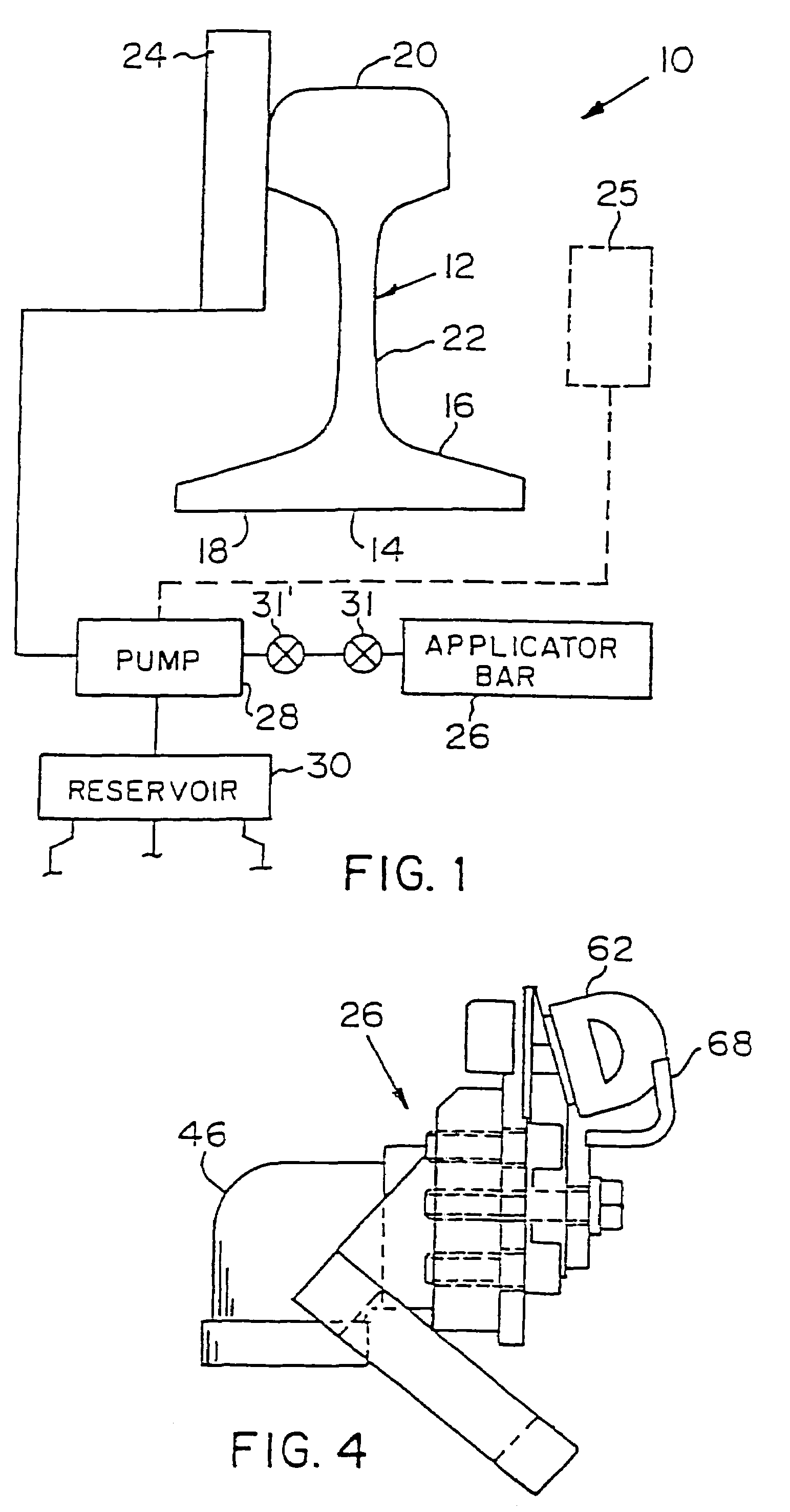
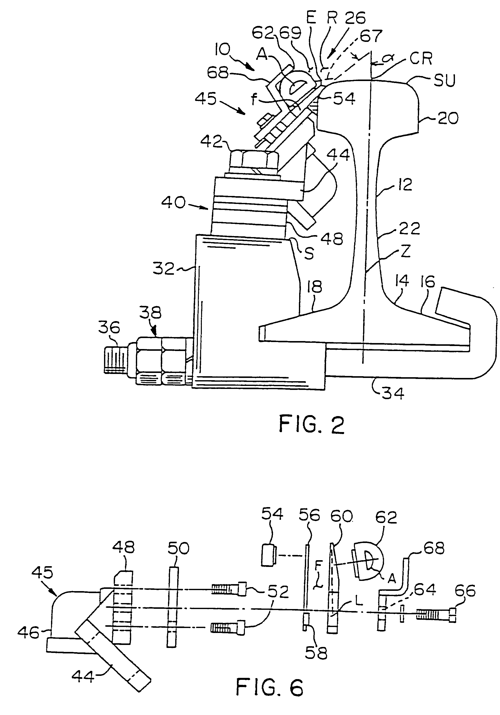
[0038]the applicator bar 26, made in accordance with the present invention, is shown in FIGS. 2-6. Referring specifically to FIGS. 2 and 3, the applicator bar 26 is mounted to the rail 12 through two oppositely positioned mounting clamps 32. Each mounting clamp 32 includes a J-bolt 34 having a J-shaped end adapted to receive the flange 16. Each J-bolt 34 includes a threaded end 36 that passes through the mounting clamp 32. The mounting clamp 32 also includes a recess adapted to receive the flange 18. Nuts and a lockwasher 38 are received at the threaded end 36 to securably hold the mounting clamp 32 to the rail 12. Spacers 40 are provided on an upper surface of the mounting clamp 32 onto which an applicator bar mounting body 44 is secured through a fastener 42. The fastener 42 has a threaded end that is threadably secured to the mounting clamp 32. The applicator bar 26 is secured to the applicator bar mounting body 44.

[0039]Referring to FIGS. 4-6, the applicator bar 26 includes a bo...

embodiment 26

[0044]FIGS. 8 and 9 show another alternative embodiment 26″ of an applicator bar similar to that shown in FIGS. 1-6, except for the below noted difference. Like reference numerals will be used for like elements.

[0045]First, the single elongated D-shaped seal 62 is eliminated and two substitute D-shaped seals 62′ and 62″ are provided only on the ends of the applicator bar, wherein a flat surface 100 of the D-shaped seals 62′ and 62″ have an adhesive that permits the respective D-shaped seals 62′ and 62″ to be attached to plates PL. A portion of the D-shaped seals 62′ and 62″ extend into the back bar 64′. Back bar 64′ is similar to back bar 64 except the L-shaped extension (bracket 68) is not provided. The D-shaped seals 62′ and 62″ extend into the bracket and contact ends of inner seal 54.

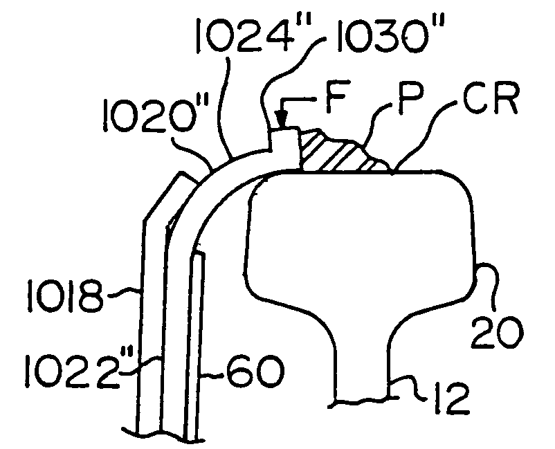
[0046]Preferably, a skirt 70′ is secured to an outer surface of the guide blade 60 and held in place by the back bar 64′. The skirt 70′ may be a rectangular metallic sheet, a polymeric material that...


PUM


Abstract

A skirt for use on an applicator bar, wherein the applicator bar includes a body and a flow passageway having an exit end defined in the body, and wherein a second section of the skirt defining a lip is adapted to coact with the body so that the second section is positioned adjacent the exit end of the body.

Description

CROSS REFERENCE TO RELATED APPLICATIONS[0001]This application claims the benefit of U.S. Provisional Patent Application Serial No. 60 / 378,821, filed May 8, 2002, which is hereby incorporated by reference.BACKGROUND OF THE INVENTION[0002]1. Field of the Invention[0003]The present invention relates to an apparatus for lubricating railroad rails or for applying friction modifiers to railroad rails.[0004]2. Description of Related Art[0005]In the operation of railroads, it has long been the practice to apply grease or friction modifier materials onto railroad rails, such as to the top of rails or sides of the rails at curves, turnouts, switches, in some cases, the sections of the track immediately before a switch, and periodically spaced along the length of the track. Such lubricants and friction modifying materials, such as grease, can either reduce or increase the friction where necessary to improve train performance and reduce wear on both the rails and the train wheels. In the case o...

Claims


Application Information

Patent Timeline
IPC IPC(8): B61K3/00
CPCB61K3/00
Inventor URMSON, JR., W. THOMASLENCO, FRANK T.MOSPAN, JOHN W.POWELL, WARD T.
Owner PORTEC RAIL PRODS
Why Eureka
Try Eureka