Method for erecting an at least two-piece main boom for a lattice-boom crane and lattice-boom crane built accordingly

a technology of lattice-boom crane and main boom, which is applied in the direction of cranes, load-engaging elements, transportation and packaging, etc., can solve the problems of only realizing, adverse effect of jib working load, and rapid reduction

Active Publication Date: 2007-09-18
TADANO DEMAG GMBH
View PDF19 Cites 7 Cited by
  • Summary
  • Abstract
  • Description
  • Claims
  • Application Information

AI Technical Summary

Benefits of technology

[0017]Another possibility for shortening the effective lever arm consists e.g. therein, to first keep the lower boom portion on the ground, maintaining the second support point, and to first erect the upper boom portion. By this erection procedure, according to which the upper boom portion rotates around the hinge of the lower boom portion, the effective lever arm of the main boom in turn is shortened. This step, according to which the effective lever arm of the main boom is shortened, either by lifting the lower or the upper boom portion, lasts as long as the tilting moment producible by the boom weight is smaller than the standing moment of the crane.
[0039]As revealed by the explanations above, the method according to the invention is especially advantageous due to the fact that by using the method, very long main booms and in particular very long main booms for lattice-boom cranes can be erected by themselves in a manner without any auxiliary means, as for example auxiliary cranes or additional super lift devices or the like being required. By using the method according to the invention, the crane succeeds virtually by itself to bring its main boom into a crane operating position. Because thus, no further auxiliary means as auxiliary cranes or the like are required, the time expenditure for the assembling and disassembling of the crane boom can be reduced substantially. Moreover, naturally no further costs for possible auxiliary means as auxiliary cranes or the like are generated.

Problems solved by technology

Such a procedure, according to which the entire boom together with a luffing tip being arranged at the jib is erected in its operating position already, can usually only be realized, however, for very light and short luffing tip jibs.
However, said supposed positive effect of such a jib consisting of a main boom and a separate fly jib, which is, even during operation, luffably arranged at the main boom, has an adverse effect on the working load of the jib, which rapidly decreases as a result of the articulated joint of the fly jib.
Hence, these cranes are not suitable to achieve high working loads, wherefore there is usually no other choice but to use a lattice-boom crane having a rigid and unbending main boom, which normally only can be erected with the aid of an additional auxiliary crane, as will be illustrated below.
Hence, the skilled person is still often confronted with the problem, either to use relatively weak cranes having for example a two-piece jib comprising for example a separate telescopic jib and a separate fly jib, which is even during operation luffably arranged at the main boom, to serve major height by the crane.
Because of the decreased working load caused by the two-piece construction of the jib, however, by means of these cranes it is not possible to carry major loads.
In the most disadvantageous case the crane would in fact tip over.
The use of such a super lift device, however, requires an increased transport and time expenditure for the assembling and disassembling of the counter boom as well as the additional counter weights.

Method used


Image

  • Method for erecting an at least two-piece main boom for a lattice-boom crane and lattice-boom crane built accordingly
  • Method for erecting an at least two-piece main boom for a lattice-boom crane and lattice-boom crane built accordingly
  • Method for erecting an at least two-piece main boom for a lattice-boom crane and lattice-boom crane built accordingly

Examples


Embodiment Construction

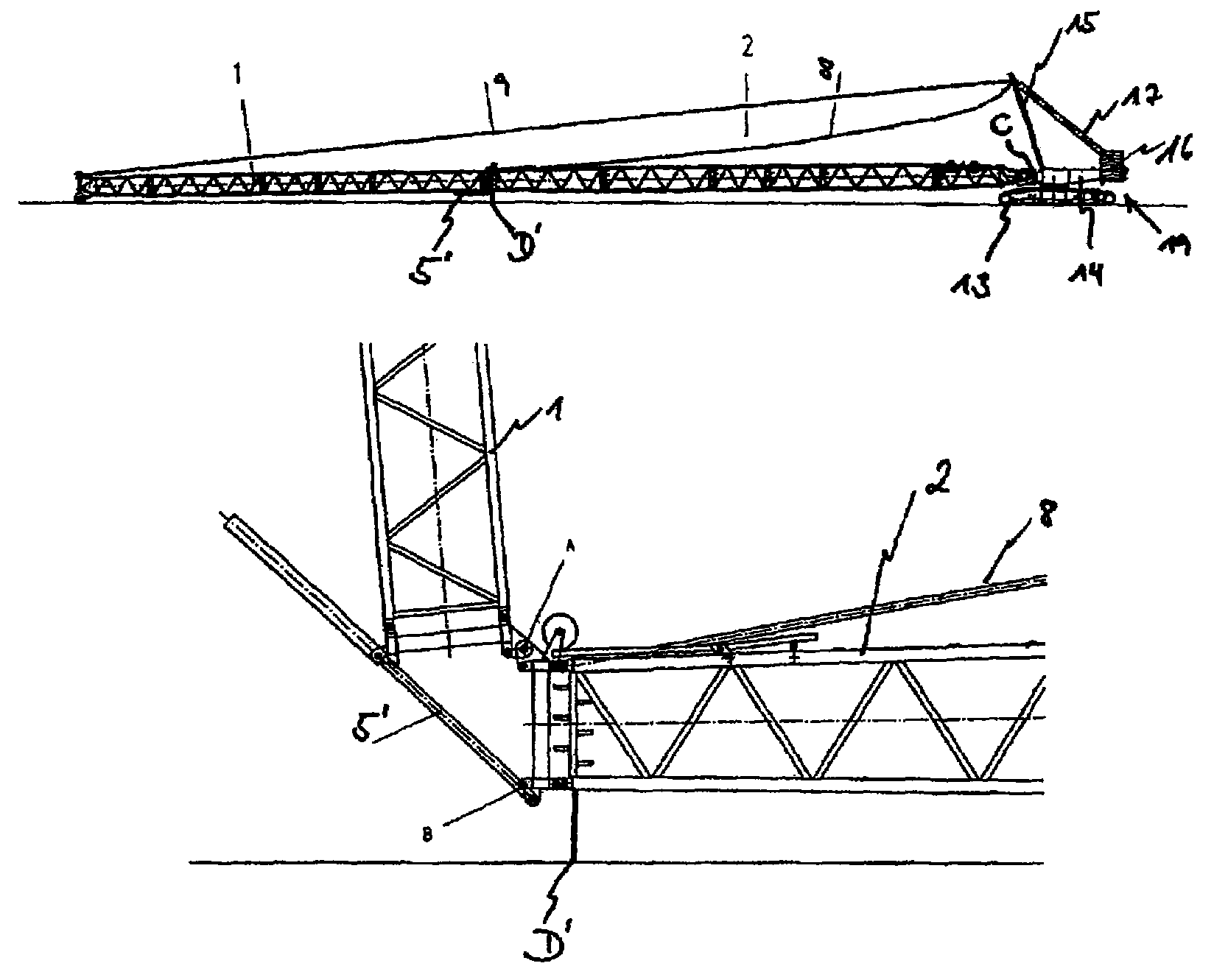
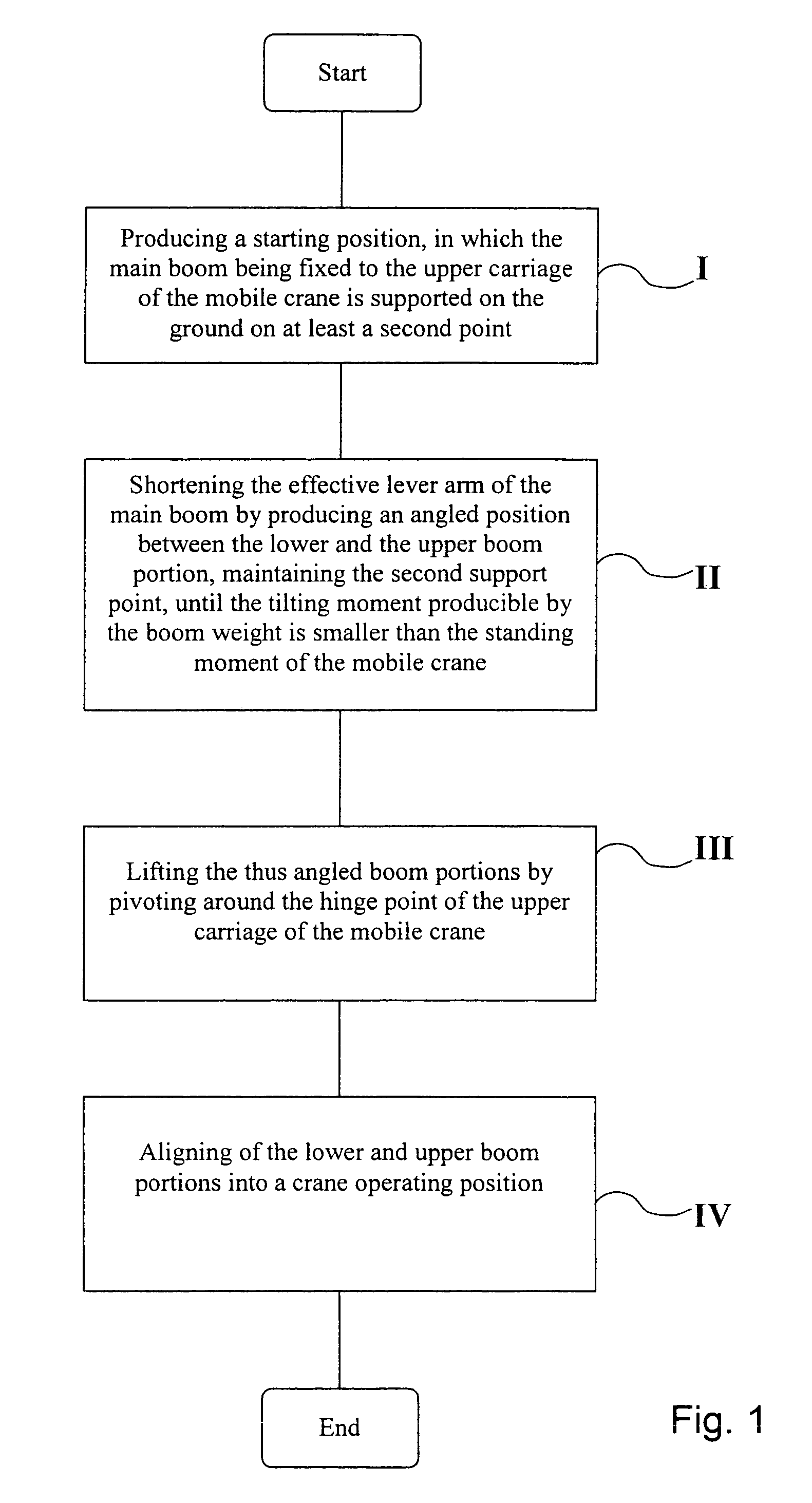
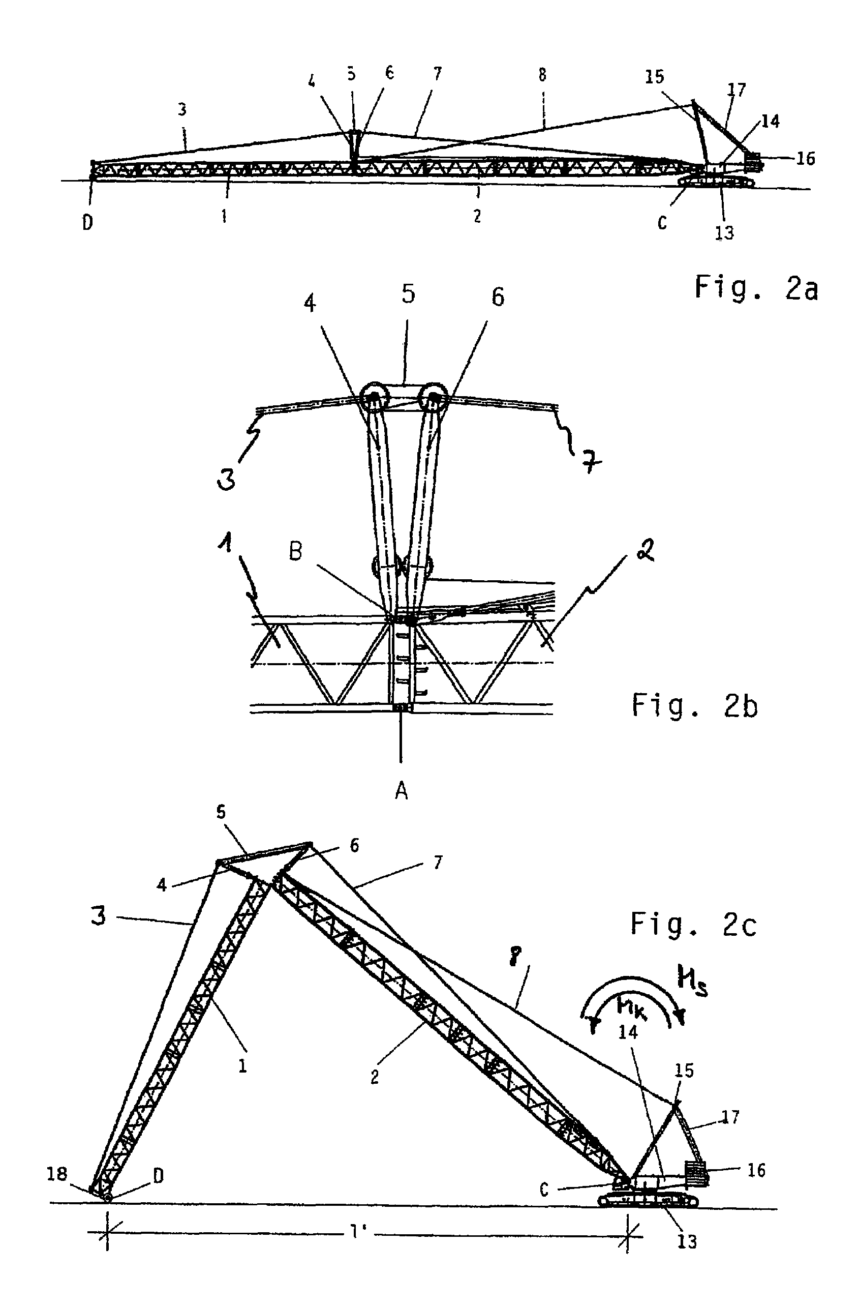
[0015]In view of the problems involved in the known methods for erecting a main boom for a lattice-boom crane, a method for erecting a main boom for a lattice-boom crane is provided according to a first aspect of the present invention, according to which the main boom can be erected without any external auxiliary means, as for example an auxiliary crane. The method is characterized in that in a first step, the main boom is aligned to its starting position, in which the main boom, which consists of a lower boom portion and an upper boom portion being jointed thereto during assembly, is supported with its lower end at a first support point on the upper carriage of the crane jointly. Further, the main boom is supported in the starting position at least on a second support point on the ground. This at least second support point can be a point of contact of the lower as well as of the upper boom portion to the ground. Naturally, also the lower as well as the upper boom portion simultaneo...


PUM


Abstract

The present invention substantially relates to a method for erecting and disassembling an at least two-piece main boom for a lattice-boom crane. The erecting and disassembling procedure results in that the geometric kinematic properties of the main boom (1, 2) are used in such a manner that during the erecting and disassembling, the effective lever arm (1′) of the main boom (1, 2) is reduced. This results from the main boom (1, 2) being bent at the hinge point (A), at which at least two boom portions (1, 2) are connected to each other, and thus an angle position is produced between the two boom portions (1, 2). Further, the invention relates to a main boom (1, 2), which can be erected by the method as well as a lattice-boom crane having such an main boom (1, 2).

Description

TECHNICAL FIELD[0001]This application is a continuation under 35 U.S.C. 111(a) of PCT / EP2004 / 003223, filed Mar. 26, 2004 and published as WO 2004 / 087557 A1, filed Oct. 14, 2004, which claimed priority under 35 U.S.C. 119 to U.S. Provisional Patent Application No. 60 / 459,669, filed Apr. 2, 2003, which applications and publication are incorporated herein by reference and made a part hereof.[0002]The present invention relates to a method for erecting a boom of a crane, and in particular a method for erecting a main boom of a lattice-boom crane subdivided into at least two jib portions. The main boom is not erected necessarily with the aid of an auxiliary crane or other additional means, but rather results from using the geometric-kinematic properties of the main boom subdivided into at least two jib portions. Moreover, the present invention relates to a main boom for a lattice-boom crane being adapted for being erected using the method according to the invention such that auxiliary mea...

Claims


Application Information

Patent Timeline
Patent Type & Authority Patents(United States)
IPC IPC(8): B66C23/42B66C23/34B66C23/82B66C23/90
CPCB66C23/82B66C23/90
Inventor DIEHL, STEFAN
Owner TADANO DEMAG GMBH
Why Eureka
Try Eureka