
Mixed wire braided device with structural integrity

a technology of braided devices and mixed wires, applied in the direction of braiding, textiles and papermaking, dyeing process, etc., can solve the problems of insufficient filter overall structural strength, inconvenient patient placement and follow-up, and added complexity to the manufacturing process

Inactive Publication Date: 2007-10-02
STRYKER EURO OPERATIONS HLDG LLC +1
View PDF4 Cites 118 Cited by
  • Summary
  • Abstract
  • Description
  • Claims
  • Application Information

AI Technical Summary

Benefits of technology

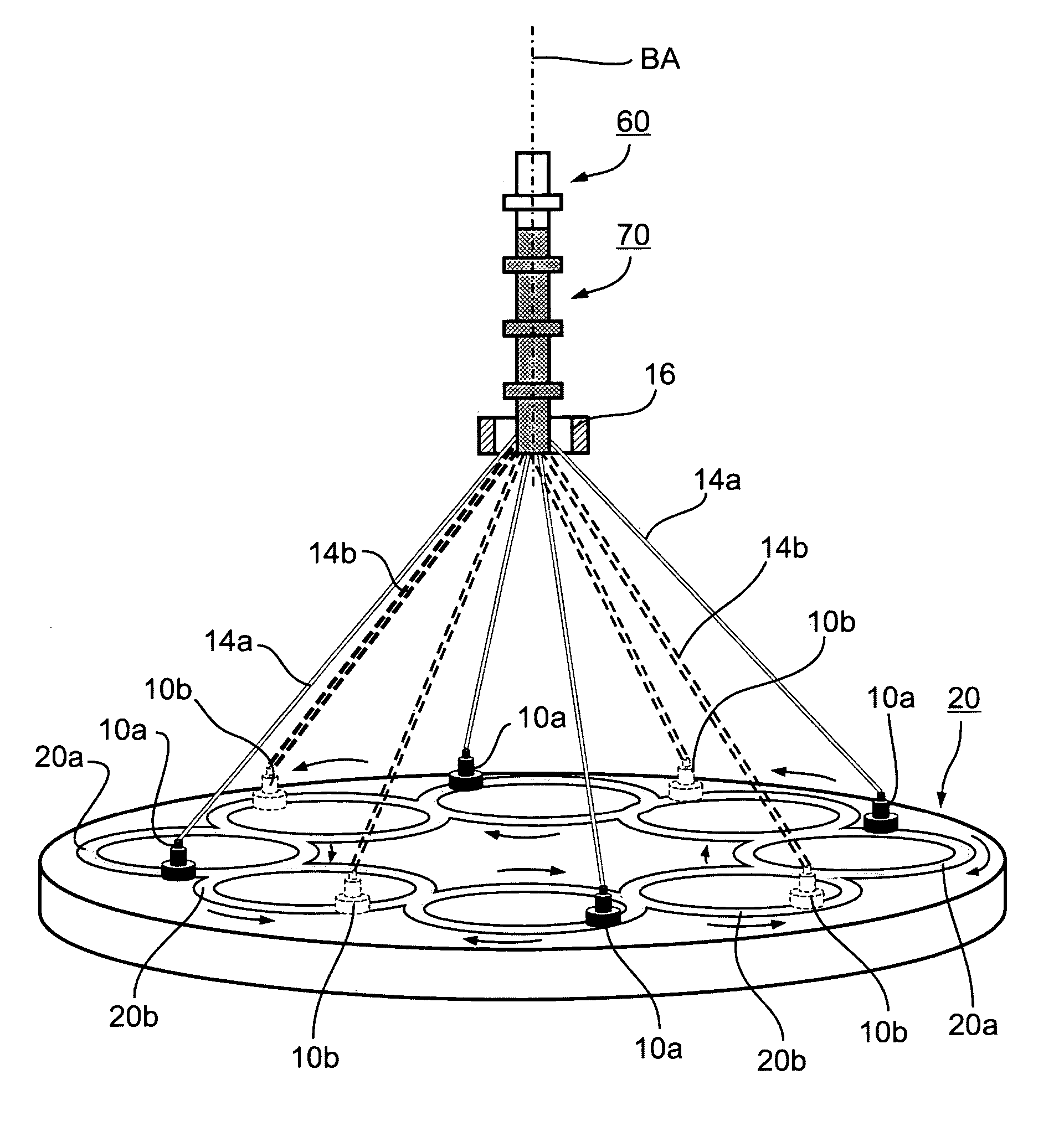
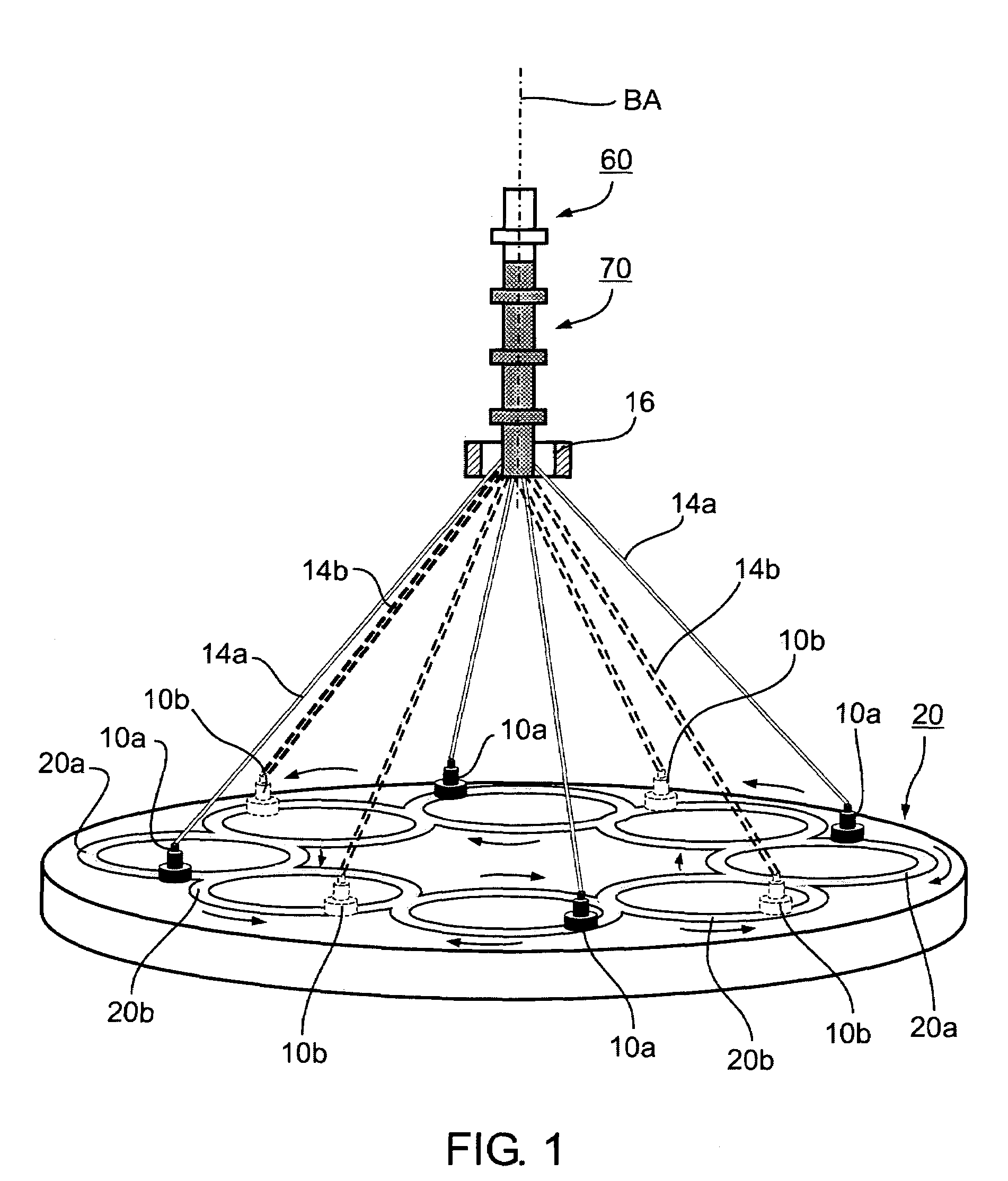
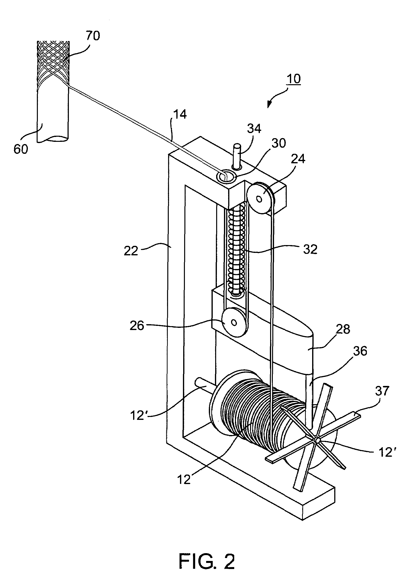
The present invention provides a braided device comprising multiple filament types, at least one of which defines an independent stable structure of a symmetrical 1×1 sub-pattern. The filament types are braided together into a single braided device exhibiting a uniform overall braid pattern. The braided device can be used as an implantable intraluminal device, stent-graft, or filter, and the braid pattern can be a single filament 1×1 braid pattern, double filament 1×1 braid pattern, or 1×2 braid pattern. The invention solves the problem of prior art braided devices having a uniform braid pattern but being made from a single filament type, which can result in disadvantages such as rigidity. The braided device of the present invention has improved rigidity and is more flexible.

Problems solved by technology

Unfortunately, in certain circumstances, filaments that are advantageous for use as a filter are insufficient to supply sufficient overall structural strength for the device.
In other cases, fine wire filaments used in the device are not readily visualized under standard fluoroscopic equipment, thus rendering precise placement and follow up of patients difficult.
The use of a three dimensional braided structure, comprising pre-shaping of the monofilaments, adds extra complexity to the manufacturing process, with a resultant increase in cost.

Method used


Image

  • Mixed wire braided device with structural integrity
  • Mixed wire braided device with structural integrity
  • Mixed wire braided device with structural integrity

Examples


first embodiment

[0064]FIG. 13 illustrates a high level flow chart of a braiding method according to the principle of the current invention, in which filament multiple filament types, comprising a first filament type hereinafter being designated F1, and a second filament type hereinafter designated F2 are braided together into a braid exhibiting a uniform braid pattern, in which filaments of type F1 define an integrated symmetrical 1×1 sub-pattern. In step 100, the braiding apparatus is selected, the selected braiding apparatus being characterized by having horn gears, the number of horn gears of the selected braiding apparatus being hereinafter designated N. As indicated above in relation to FIG. 10-12, for a single filament 1×1 braid pattern, the number of carriers is equal to the number of horn gears.

[0065]In step 110, the braid pattern to be utilized in the operation of the braiding apparatus selected in step 100 is selected. As indicated above, the braid pattern is chosen from the possible brai...

second embodiment

[0073]FIG. 15 illustrates a high level flow chart of a braiding method according to the principle of the current invention, in which multiple filament types, comprising a first filament type hereinafter being designated F1, and a second filament type hereinafter designated F2, and a third filament type hereinafter being designated F3, are braided together into a braid exhibiting a uniform braid pattern, in which filaments of type F1 define a first integrated symmetrical 1×1 sub-pattern and filaments of type F2 define a second integrated symmetrical 1×1 sub-pattern. The braiding method is herein being described as having two individual integrated symmetrical 1×1 sub-patterns, however this is not meant to be limiting in any way. In another embodiment three or more multiple integrated sub-patterns are defined within an overall uniform braid pattern without exceeding the scope of the invention.

[0074]In a preferred embodiment the overall braid pattern is a 1×2 braid pattern as described ...


PUM

PropertyMeasurementUnit
diameteraaaaaaaaaa
diameteraaaaaaaaaa
rigidityaaaaaaaaaa

Abstract

A braided device comprising: filaments of a first type and of a second type, the second type differing from the first type in at least one characteristic; the first type of filaments defining an integral symmetrical 1×1 sub-pattern; and the combination of the first type of filaments and the second type of filaments being braided together into a braided device exhibiting a uniform braid pattern.

Description

CROSS-REFERENCE TO RELATED APPLICATIONS[0001]This application claims priority from U.S. Provisional Patent Application Ser. No. 60 / 532,571 file Dec. 29, 2003 entitled “Mixed Wire Braided Device with Structural Integrity” the entire contents of which are incorporated herein by reference.BACKGROUND OF THE INVENTION[0002]The invention relates generally to the field of braided devices and more particularly to a braided devices having multiple filament types.[0003]Braiding is used in a wide variety of different fields, for example, textiles, electronics, aerospace, and medicine, for performing a variety of different applications, for example, harnessing, shielding, and / or reinforcing, materials and structures, requiring special or high performance properties, characteristics, and behavior. In medicine, braiding is used to produce, among others, implantable intraluminal devices, including stents, stent-grafts, preventing devices and stroke preventing devices. Stents are used to support di...

Claims


Application Information

Patent Timeline
Patent Type & Authority Patents(United States)
IPC IPC(8): D04C1/02D04C1/06D06P7/00
CPCD04C1/02D04C3/40D04C3/18D04C1/06
Inventor NISHRI, BOAZRAPAPORT, AVRAHAMCIBULSKI, GILADFOUKS, YANIV
Owner STRYKER EURO OPERATIONS HLDG LLC
Learn More