Portable gun support case

a gun and support case technology, applied in the field of portable gun support cases, can solve the problems of insufficient firm support for the gun, low support capacity of the gun, and high cost of the gun support in this paten

Inactive Publication Date: 2007-10-16
FLAMBEAU
View PDF16 Cites 47 Cited by
  • Summary
  • Abstract
  • Description
  • Claims
  • Application Information

AI Technical Summary

Benefits of technology

[0007]In a principle aspect, the present invention comprises a portable gun support case having gun support members firmly held in place on the case. When the case is in an open condition, retaining members hold the support members firmly in place and thereby hold a gun mounted on the support members firmly in place. When the case is in a closed condition, the same retaining members hold the case firmly closed. The case has a lower box and an upper box including two longitudinal box sections pivotally mounted on the lower box. The support members, gun repair tools and maintenance materials may be carried in the lower box. When the box is open, the support members may be placed in upright positions adjacent walls of the lower box. The retaining members then may be moved into holding engagement with the support members. When the support members are removed from their upright positions, the upper box may be pivotally closed above the lower box along a longitudinal center line formed by the two longitudinal box sections of the upper box and in engagement with the lower box. When the upper box engages the lower box, outward projections at opposite ends of the upper box are engaged by the retaining members to hold the case firmly closed. The case is carried by a handle affixed to the upper box.

Problems solved by technology

When such guns are transported for use at different locations such as the open field or target ranges, it is often necessary to clean or otherwise maintain them without the benefit of a fixed gun support and where maintenance materials aren't available.
This is a relatively cumbersome combination with respect to portability and may not provide sufficiently firm support for the gun.
The gun supports in this patent appear to be relatively expensive and the carrying case does not provide storage space for tools and maintenance parts and materials.

Method used


Image

  • Portable gun support case
  • Portable gun support case
  • Portable gun support case

Examples


Embodiment Construction

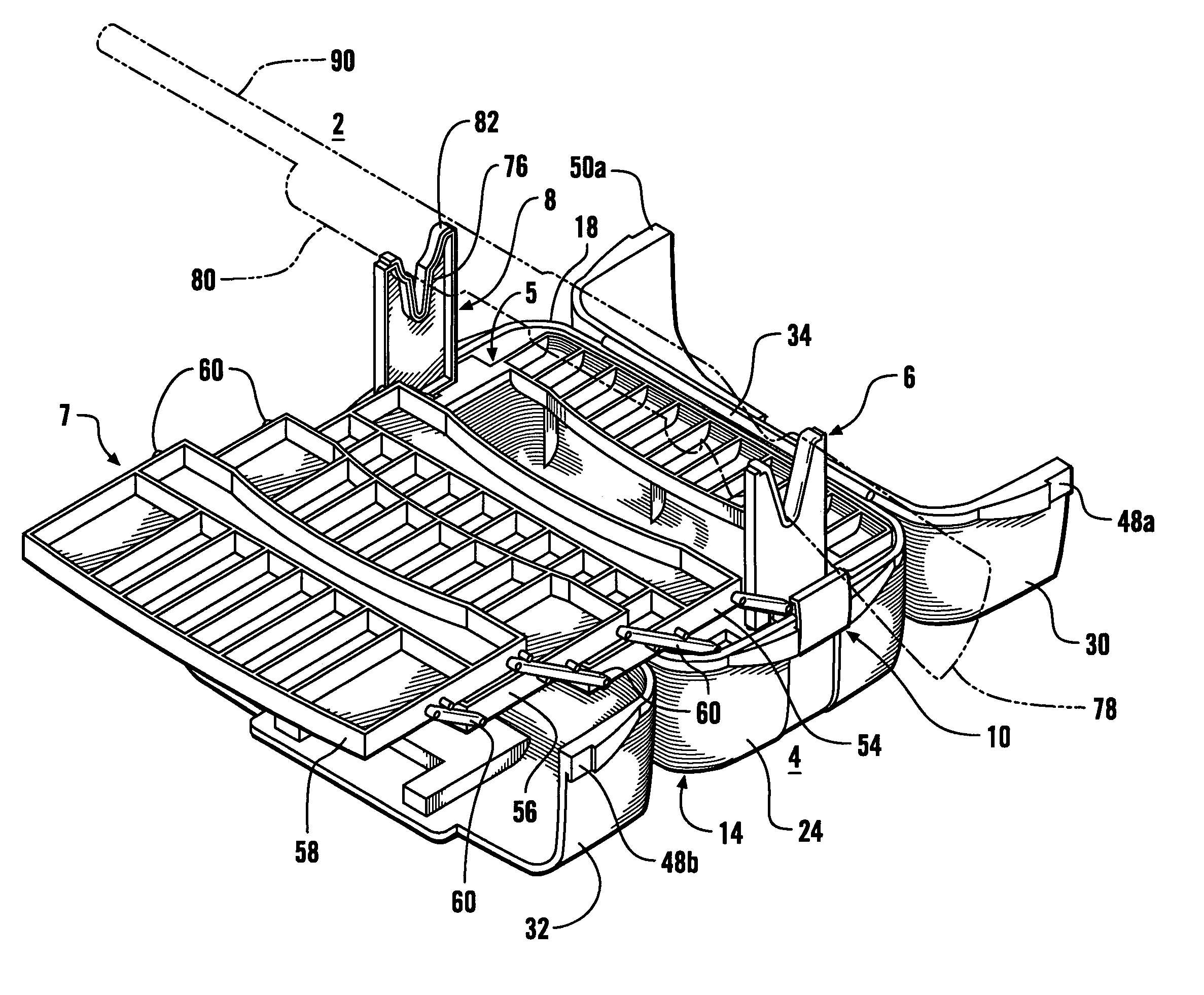
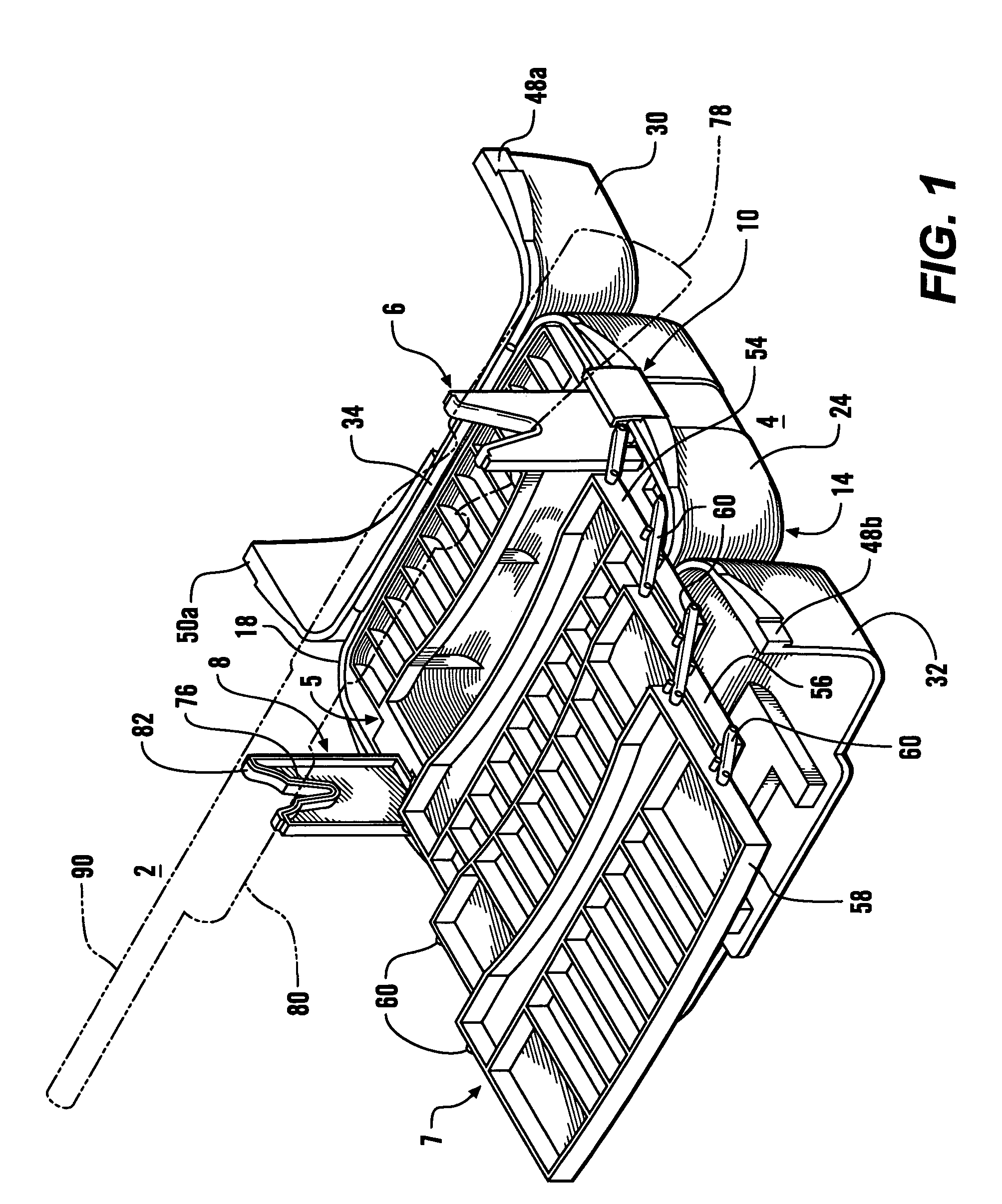
[0020]Referring generally to the figures, a gun 2, a case 4, support members or yokes 6 and 8 for supporting the gun, and retaining members 10 and 12 are illustrated. The case includes a support frame 5 and a cantilevered storage tray section 7 mounted on the support frame 5. The support frame 5 also includes an additional storage tray 52. The retaining members 10 and 12 alternatively hold the case 4 closed or hold the yoke members 6 and 8 in place, as will be described in greater detail hereinafter.

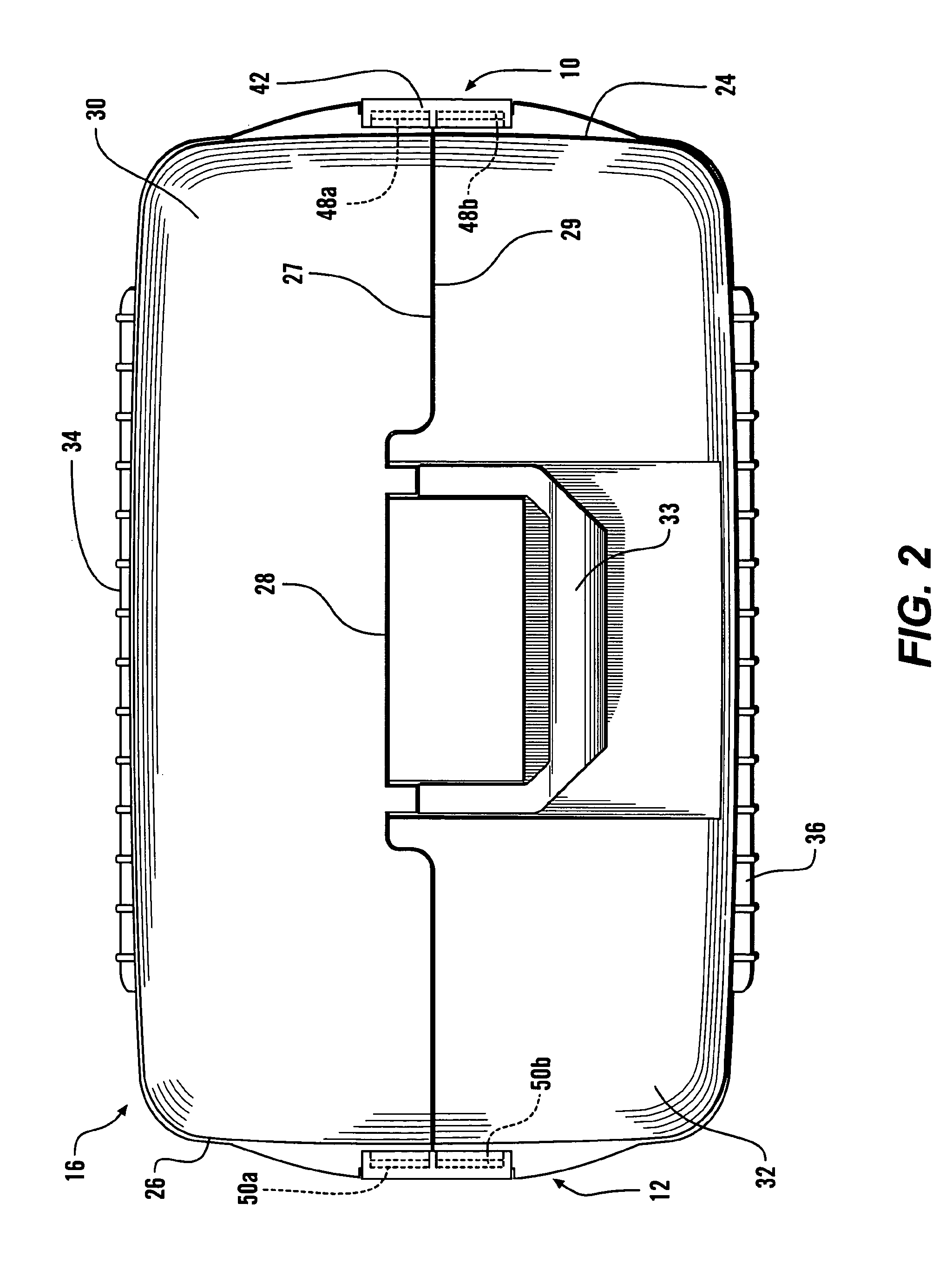
[0021]The case 4 comprises a lower elongated box 14 open upwardly when the case 4 is sitting on a level surface and an upper cover or box 16 which is open downwardly and engages the entire perimeter 18 of the lower box 14 when the case 4 is closed. The lower box 14 has a pair of longitudinal or lengthwise sidewalls 20 and 22 and a pair of facing end sidewalls 24 and 26 each connected to the lengthwise sidewalls 20 and 22. The connected sidewalls 20, 24, 22 and 26 together form the aforem...


PUM


Abstract

A portable gun support case having gun support members firmly held in place on the case by retaining members attached to the case. The case has a lower box and an upper box which includes two longitudinal box or cover sections pivotally mounted on the lower box. When the box is open, the support members may be placed in upright positions adjacent walls of the lower box. The retaining members then may be moved into firm holding engagement with the support members. When the support members are removed from their upright positions, the upper box may be pivotally closed above the lower box along a center line formed by the two longitudinal cover sections and in engagement with the lower box. When the upper box engages the lower box, outward projections at opposite ends of the upper box are engaged by the retaining members to hold the case firmly closed.

Description

BACKGROUND OF THE INVENTION[0001]1. Field of the Invention[0002]This invention relates to a support case for a gun. More particularly, the invention relates to a readily portable support case for rifles or shotguns which may be quickly set up to provide support for the gun.[0003]2. Description of the Related Art[0004]When guns such as rifles and shotguns are cleaned or maintained, it is desirable that they be held in a fixed position during the maintenance work. Of course, it is also necessary to have the needed tools and maintenance material readily available. When such guns are transported for use at different locations such as the open field or target ranges, it is often necessary to clean or otherwise maintain them without the benefit of a fixed gun support and where maintenance materials aren't available. Thus, there is a need for a portable gun holder or support which provides firm support for the gun while it is being cleaned or repaired. Such a gun support can also be used t...

Claims


Application Information

Patent Timeline
Patent Type & Authority Patents(United States)
IPC IPC(8): F41A9/62
CPCF41C33/06F41A23/02
Inventor COOK, GREGORY A.PHILIPS, III, CHARLES E.
Owner FLAMBEAU
Why Eureka
Try Eureka