

Lamp apparatus for vehicle
a technology for vehicle lighting and apparatus, which is applied in the direction of lighting and heating apparatus, cycle equipment, lighting support devices, etc. it can solve the problems of reducing the life power dissipation, and affecting the operation of the light emitting diodes, so as to reduce the weight of the lamp unit and reduce the number of parts. , the effect of reducing the number of man-hours in assembly
- Summary
- Abstract
- Description
- Claims
- Application Information
AI Technical Summary
Benefits of technology
Problems solved by technology
Method used
Image

Examples
second embodiment
[0055]Now, an example wherein the present invention is applied to a rear portion of a vehicle body of the motorcycle 1 is described as a second embodiment with reference to FIGS. 4 to 6.
[0056]Referring to FIG. 4, a rear cowl 35 of the motorcycle 1 and the outer periphery of the seat rail (not shown) are connected to a rear portion of the vehicle body frame 2 which is covered with the rear cowl 35. A seat 36 is disposed at an upper portion of the rear cowl 35, and a tail lamp 37 is provided at a rear end of the rear cowl 35. Further, a pair of left and right license brackets 40, 40 are provided at a lower portion of the rear cowl 35 and extend downwardly and rearwardly.
[0057]Referring to FIG. 5, each of the license brackets 40 is formed from an aluminum die-cast material such that it is elongated in its extension direction and tapers as viewed in a side elevation. The license brackets 40 are disposed in a spaced relationship from each other in the leftward and rightward directions, a...
third embodiment
[0093]Subsequently, the present invention is described.
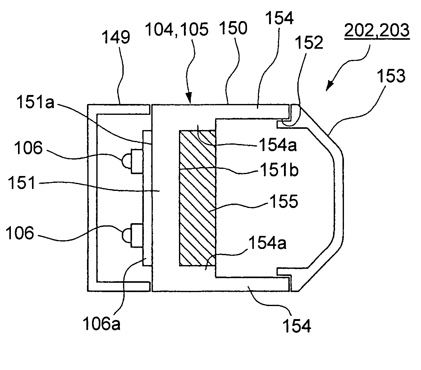
[0094]The present embodiment uses blinkers 302 and 303 shown in FIG. 12 in place of the blinkers 202 and 203 described hereinabove. Each of the blinkers 302 and 303 includes a resistance circuit 255 attached to the inner side of the circumferential wall 154 of the lamp body case 150. The resistance circuit 255 is attached, for example, in a state wherein it is in close contact with but is insulated from the inner side of a lower portion of the circumferential wall 154. The light emitting diodes 106 are attached at a location spaced from the resistance circuit 255 of the lamp body case 150.
[0095]According to the third embodiment described above, similar operation and effects to those of the second embodiment described above are exhibited. Further, since the light emitting diodes 106 and the resistance circuit 255 are provided in a spaced relationship by a greater distance from each other, heat transmission between them can be fur...
fourth embodiment
[0096]Subsequently, the present invention is described.
[0097]The present embodiment uses blinkers 402 and 403 shown in FIG. 13 in place of the blinkers 302 and 303 described hereinabove. In each of the blinkers 402 and 403, the internal space of the lamp body case 150 is partitioned into two parts in which the resistance circuit 255 and an electric circuit 256 are accommodated individually. Here, the electric circuit 256 is, for example, a constant-current circuit and, in the case of a blinker, a relay circuit and so forth for the blinker. The internal space of the lamp body case 150 is divided, for example, in an upward and downward direction by a partition wall 150a, and the resistance circuit 255 and the electric circuit 256 are accommodated individually in the divisional spaces.
[0098]According to the fourth embodiment described above, similar operation and effects to those of the third embodiment described hereinabove are exhibited. Further, since the resistance circuit 255 and ...
PUM
 Abstract
Description
Claims
Application Information