Hypotube with improved strain relief

a technology of hypotube and strain relief, which is applied in the field of improved hypotube, can solve the problems of time-consuming and difficult task of advancing the catheter assembly to position the balloon across the stenosis, and achieve the effect of increasing the flexibility of the first section and enhancing the transition

Inactive Publication Date: 2007-11-13
BOSTON SCI SCIMED INC
View PDF48 Cites 96 Cited by
  • Summary
  • Abstract
  • Description
  • Claims
  • Application Information

AI Technical Summary

Benefits of technology

[0012]An improved hypotube for an intravenous device is disclosed which comprises a tubular shaft comprising a tubular wall defining a lumen and a main section connected to the distal section. The distal section of the tubular shaft comprises a first section connected to a second section. The first section is connected to the main section and disposed between the main section and the second section. The first section comprises at least one slit extending at least partially through the tubular wall for increasing t...

Problems solved by technology

Advancing the catheter assembly to position the balloon across a stenosis can be a difficult and time consuming task due to the narrow and tortuous passages through which the catheter assembly must be passed.
One problem associated with connecting a relatively stiff tubular member, such as a ...

Method used


Image

  • Hypotube with improved strain relief
  • Hypotube with improved strain relief
  • Hypotube with improved strain relief

Examples


Embodiment Construction

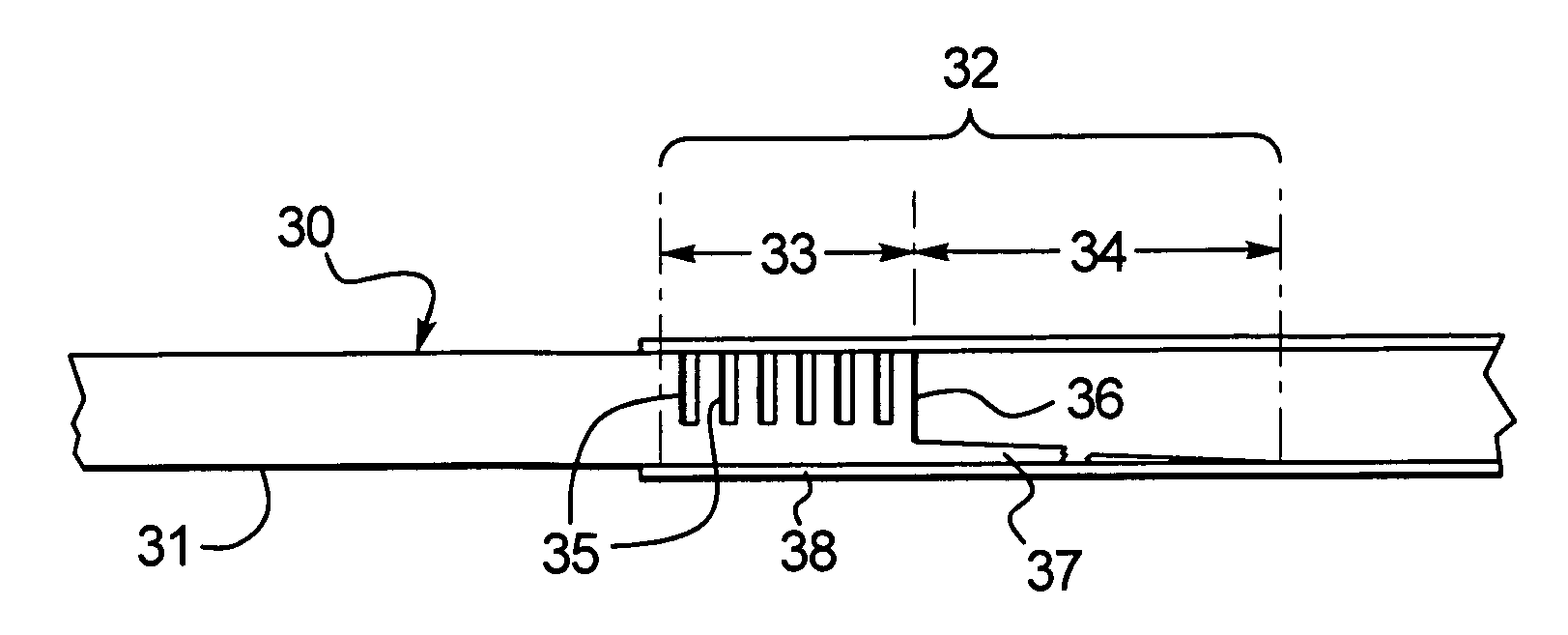
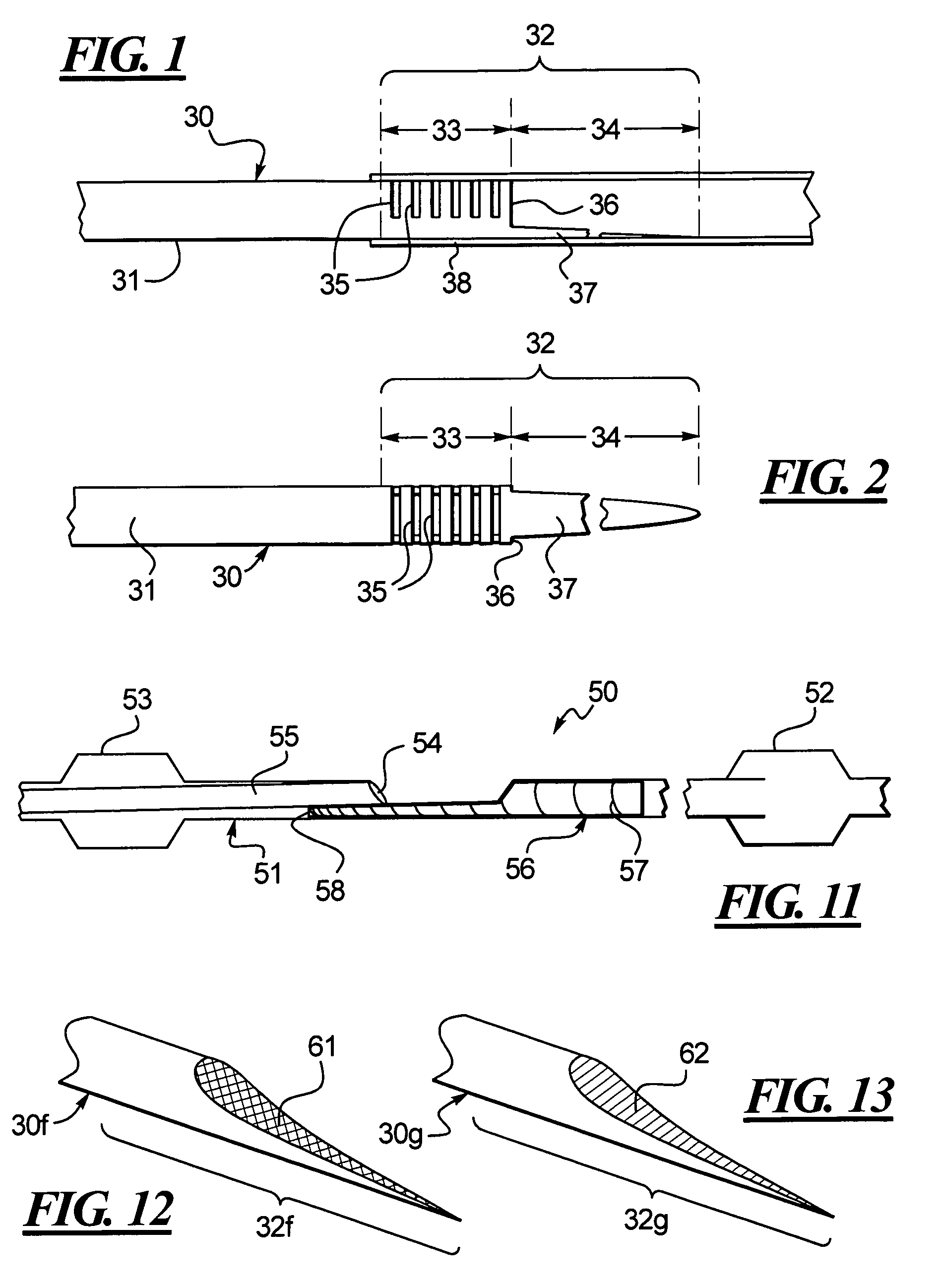
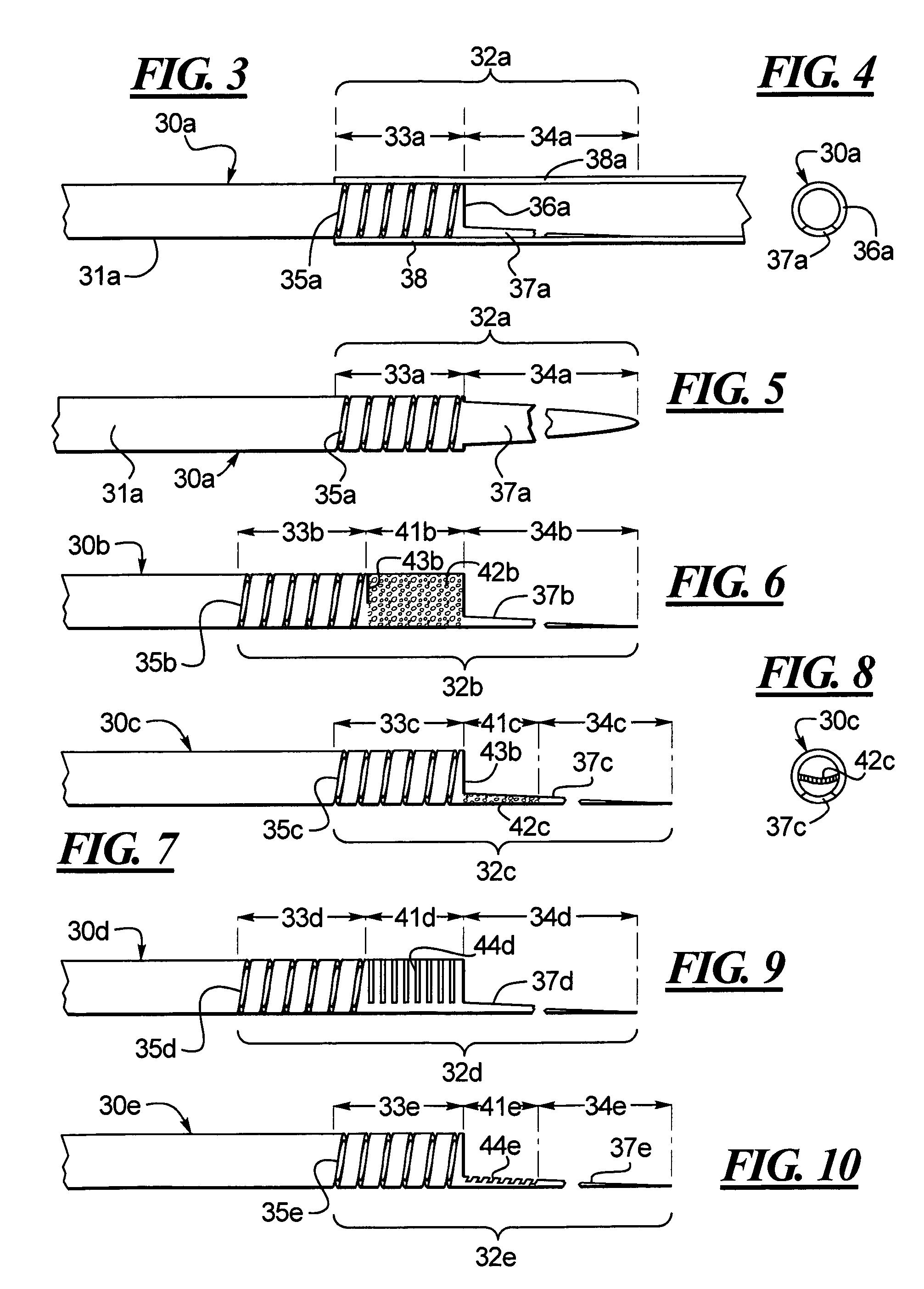
[0040]One embodiment of an improved hypotube 30 is disclosed in FIG. 1 whereby the hypotube 30 includes a tubular shaft having a main section 31 connected to a distal section 32. The distal section 32 can be divided into a first section 33 and a second section 34. The first section 33 is integrally connected to the main section 31 and, to increase the flexibility of the first section 33, one or more of slits or cuts is provided in the first section 33. To further improve the function of the distal section 32 as a transition element, the second section 34 includes a cut-out portion 36 whereby the tubular wall is cut away leaving a stinger that is partially shown at 37 in FIGS. 1 and 2. The stinger can also be tapered. The distal section 32 of the hypotube 30 is received in a catheter 38. Thus, the distal section 32 includes at least two distinct sections 33, 34, both with different flexibilities. The first section 33, by way of the slits or cuts 35 is more flexible than the main sect...


PUM

PropertyMeasurementUnit
Lengthaaaaaaaaaa
Flexibilityaaaaaaaaaa

Abstract

A hypotube for an intravenous catheter device is disclosed which includes a tubular shaft having a tubular wall defining a lumen. The shaft includes a main section integrally connected to a distal section. The distal section includes a first section connected to the second section and disposed between the second section and the main section. The second section includes an elongated stinger.

Description

BACKGROUND[0001]1. Technical Field[0002]An improved hypotube for an intravascular catheter is disclosed. More specifically, an improved hypotube for use with a catheter is disclosed that provides improved strain relief or transitioning stiffness characteristics between a distal end of the hypotube and a proximal end of the catheter.[0003]2. Description of the Related Art[0004]Intravascular catheters are widely used for a variety of diagnostic and therapeutic purposes. Specifically, angioplasty has been developed as an alternative to bypass surgery for treating vascular diseases or other conditions that occlude or reduce blood flow in a patient's vascular system. Balloon angioplasty has proven to be a useful and often a preferred treatment for coronary diseases that cause blockages, also known as stenosis, in coronary arteries as well as other parts of the vascular system.[0005]One current angioplasty technique makes use of a single operator exchange or rapid exchange catheter assemb...

Claims


Application Information

Patent Timeline
IPC IPC(8): A61M25/00A61F2/82A61M25/06
CPCA61M25/0662A61M25/0054A61M25/0138
Inventor EIDENSCHINK, TRACEE E. J.
Owner BOSTON SCI SCIMED INC
Why Eureka
Try Eureka