Vending machine lock assembly

a technology for vending machines and locks, applied in the field of vending machine locks, can solve the problems of poor access control known vandalism of prior art vending machine locks

Inactive Publication Date: 2007-11-20
STANLEY WORKS THE
View PDF41 Cites 17 Cited by
  • Summary
  • Abstract
  • Description
  • Claims
  • Application Information

AI Technical Summary

Problems solved by technology

Prior art vending machine locks have been known to be subject to vandalism, for example, by drilling.
In addition, many of the prior art vending machine locks provide poor access control.

Method used


Image

  • Vending machine lock assembly
  • Vending machine lock assembly
  • Vending machine lock assembly

Examples


Embodiment Construction

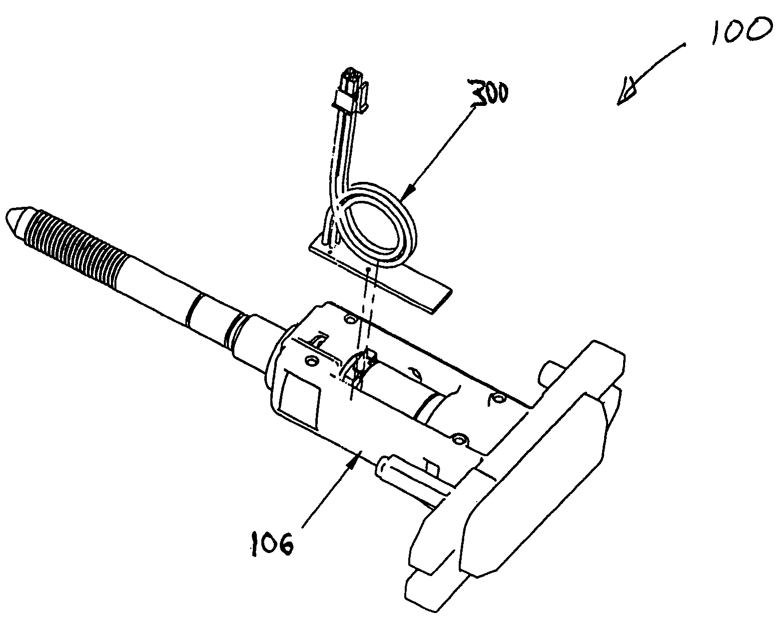
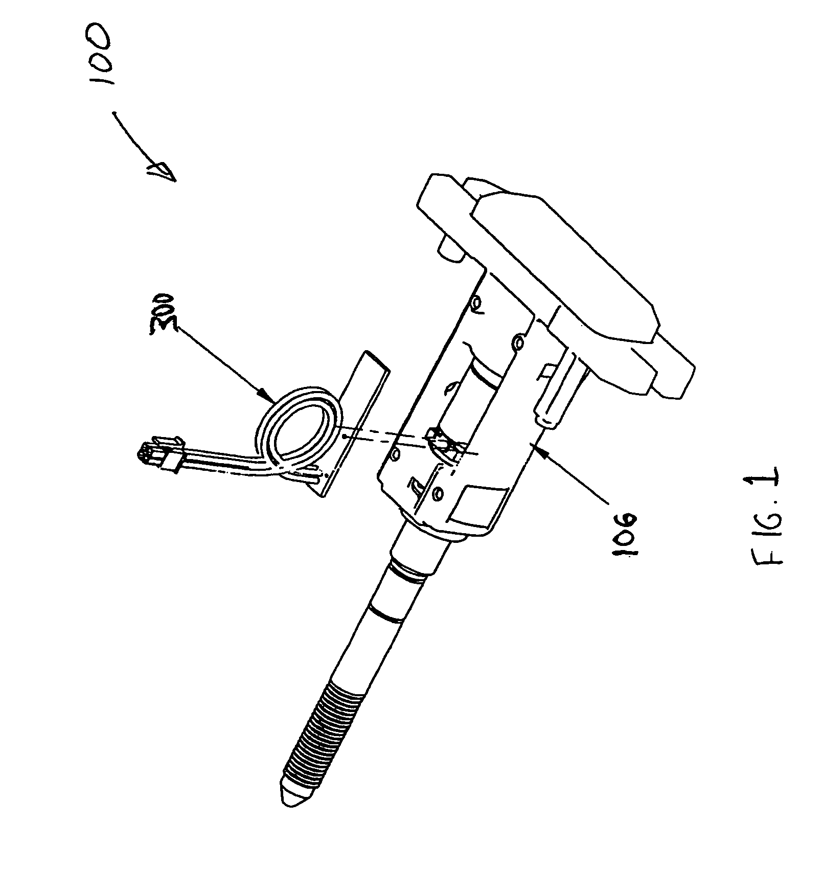
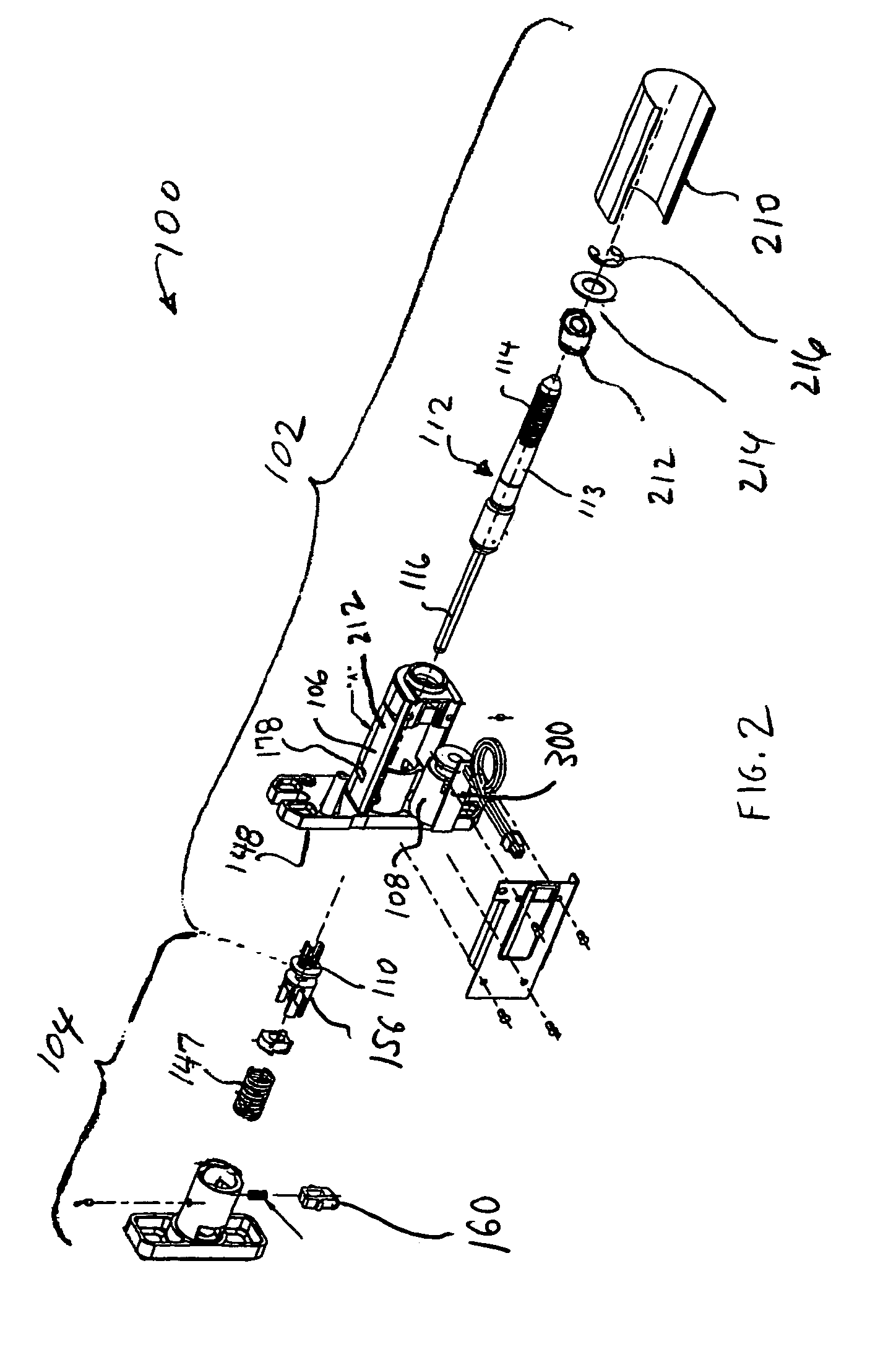
[0024]The lock assembly 100 according to an embodiment of the present invention comprises, among other components, a latch assembly 102 and a handle assembly 104.

[0025]The latch assembly 102 includes a steel case shell 106, which houses a solenoid assembly 108. The solenoid contains coil windings, which, when energized, creates an electromagnetic field that drives an internal plunger 111 (see FIG. 7) that extends through the middle of the coil windings. The distal end of the internal plunger 111 mates with a plastic plunger attachment 110. The plunger 111 and plunger attachment 110 both have a central aperture.

[0026]A locking bolt assembly 112, shown in greater detail in FIG. 3, is in the form of an assembly that includes a bolt portion 113 having threads 114, and a driver portion 116. End portion 118 of the driver portion 116 is received within an axial opening (not shown) in end 120 of bolt portion 113. A pin 122 is received in an opening 124 in a side portion of the bolt portion ...


PUM


Abstract

A wireless lock assembly includes a latch assembly that includes a wireless, electrically operated latching component, and a manually movable latching component. The wireless, electrically operated latching component is movable between activated and inactivated positions. The electrically operated latching component will remain in the activated position for a predetermined period of time, after which it will return to the inactivated position. The lock assembly also includes a handle assembly that is manually movable from a non-enabled position into an enabled position when the electrically operated latching component is moved to its activated position. When the handle assembly is in its enabled position, it can be manually moved so as to move the manually movable latching component from a locking condition to a releasing condition. The handle assembly can be manually moved from its non-enabled position to its enabled position by manual engagement and depression of an exposed surface portion thereof.

Description

CROSS-REFERENCE TO RELATED APPLICATIONS[0001]This application claims the benefit of priority from U.S. Provisional patent application Ser. No. 60 / 655,724, filed Feb. 24, 2005, the entire content of which is incorporated herein by reference.BACKGROUND OF THE INVENTION[0002]1. Field of the Invention[0003]The present invention relates to vending machine locks.[0004]2. Description of Related Art[0005]Prior art vending machine locks have been known to be subject to vandalism, for example, by drilling. In addition, many of the prior art vending machine locks provide poor access control. Several other shortcomings also exist. It is therefore an object of the present invention to provide an improved vending machine lock.SUMMARY OF THE INVENTION[0006]According to an aspect of the invention, a wireless lock assembly is provided. The lock assembly includes a latch assembly that includes a wireless, electrically operated latching component, and a manually movable latching component. The wireles...

Claims


Application Information

Patent Timeline
Patent Type & Authority Patents(United States)
IPC IPC(8): E05B13/00
CPCE05B5/003G07F9/10E05B47/0673E05B15/1614E05B47/0004Y10S292/31E05B2047/0074G07C9/00182Y10T70/5367Y10T70/5761Y10T70/577Y10T70/5827Y10T70/5978Y10T70/7102Y10T70/713Y10T292/1099Y10T292/57Y10T292/96
Inventor PRIEST, WILLIAM L.PETERSON, STEPHEN A.MCKIBBEN, AARON
Owner STANLEY WORKS THE
Why Eureka
Try Eureka