
Contact lens with controlled shape

a technology of contact lenses and shape, applied in the field of contact lenses, can solve the problems of discomfort in the eye, affecting the normal use of the eye, and affecting the effect of the eye position

Active Publication Date: 2007-11-20
TRU FORM OPTICS
View PDF6 Cites 16 Cited by
  • Summary
  • Abstract
  • Description
  • Claims
  • Application Information

AI Technical Summary

Problems solved by technology

However, a problem associated with known contact lenses is maintaining the position of a contact lens on the human eye.
Because the contact lens has specially tailored optical properties that depend on the orientation of the visual axis vis-à-vis the person's eye, the movement of the contact lens can cause the person's vision to become distorted.
In addition, the shifting of the contact lens can cause discomfort in the person's eye.
These two factors cause many patients to be reluctant to wear specially tailored contact lenses.
However, this type of contact lens is often uncomfortable for the patient.
However, the patient must have a significant amount of astigmatism or corneal deformation for this type of lens to be a viable option.
Further, a patient who requires only a slightly toric lens would experience more lens rotation while wearing the contact lens and which would create more visual problems.
The problems associated with seating specially tailored contact lenses have resulted in patients with unmet optical needs.
Furthermore, the business of specially tailored contact lenses is limited because only a relatively small fraction of patients can or will use these types of specially tailored contact lenses.

Method used


Image

  • Contact lens with controlled shape
  • Contact lens with controlled shape
  • Contact lens with controlled shape

Examples


Embodiment Construction

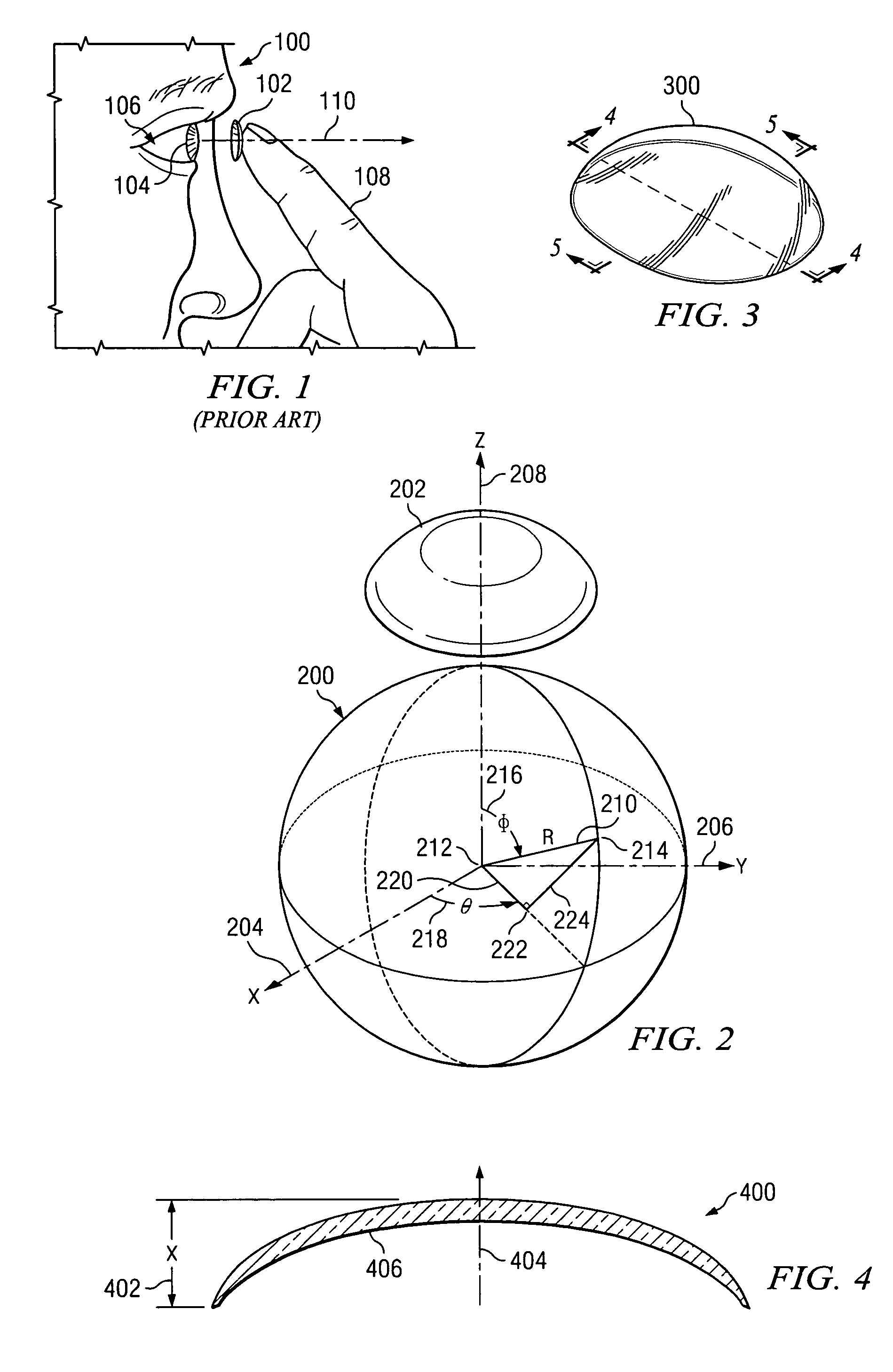
[0023]With reference now to the figures and in particular with reference to FIG. 1, FIG. 1 shows a prior art method of a human 100 placing contact lens 102 on cornea 104 of eye 106, in accordance with an illustrative embodiment of the present invention. Contact lens 102 of the present invention may be placed onto cornea 104 of eye 106 by any convenient method, aside from using finger 108 as shown. The contact lenses of the present invention may also be sized and dimensioned for use on animal eyes, or may be sized and dimensioned as optical lenses on optical devices.

[0024]FIG. 2 shows a reference system 200 for describing the shape of contact lens 202, in accordance with an illustrative embodiment of the present invention. Contact lens 202 may correspond to contact lens 102. Reference system 200 includes X-axis 204, Y-axis 206, and Z-axis 208. Each axis is orthogonal (perpendicular) to the other, such that a ninety degree angle exists between each axis. Any two axes are in the same p...


PUM


Abstract

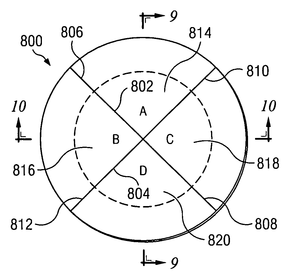
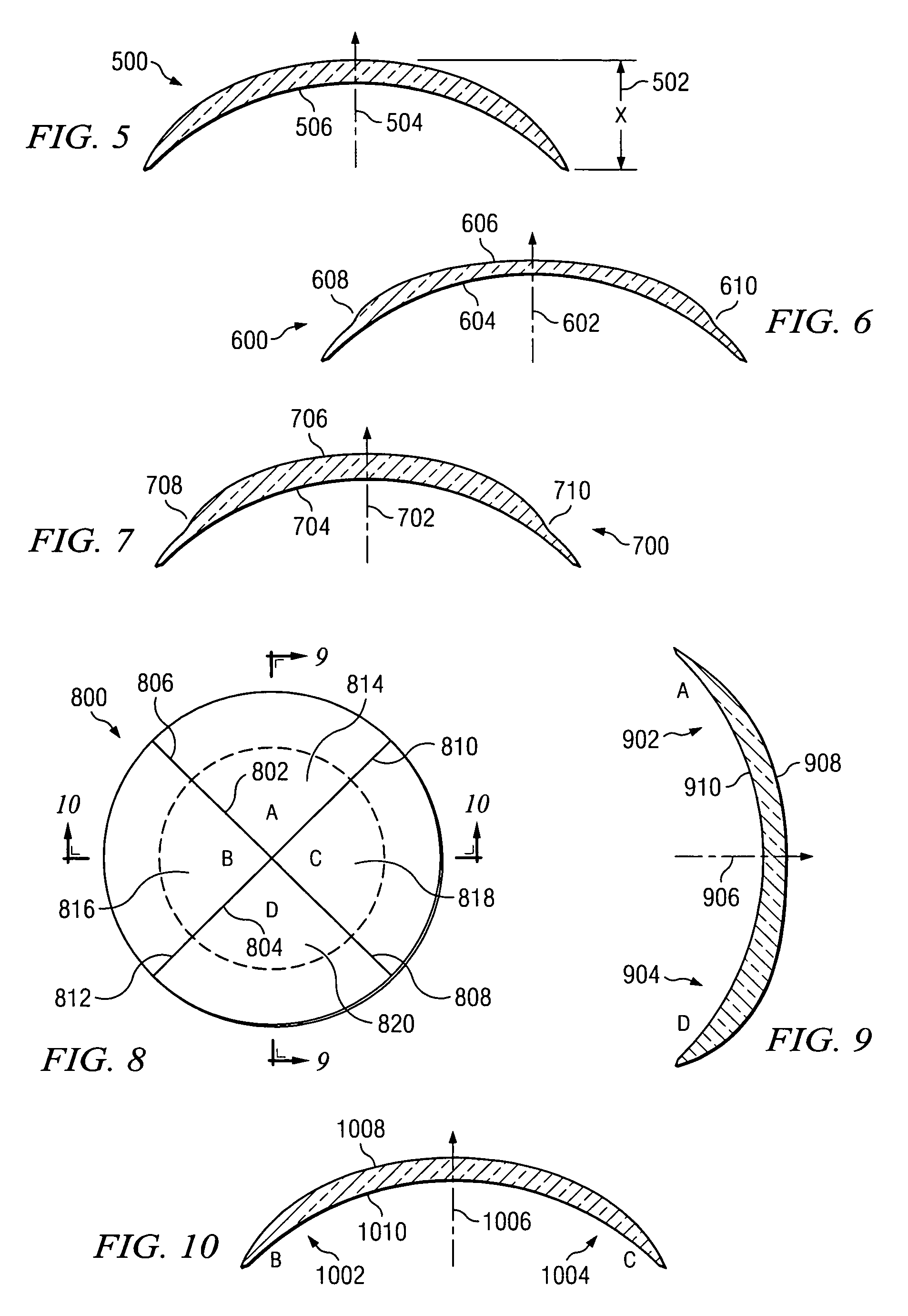
A contact lens including a single component lens sized and dimensioned for placement on a cornea of an eye. The single component lens includes a first base curve for the back surface of the single component lens, wherein the first base curve is associated with the first sub-axis; a second base curve for the back surface, wherein the second base curve is associated with the second sub-axis; a third base curve for back surface, wherein the third base curve is associated with the third sub-axis; and a fourth base curve for the back surface, wherein the fourth base curve is associated with the fourth sub-axis. The first base curve, the second base curve, the third base curve, and the fourth base curve are selected to form a shape for the back surface of the single component lens that conforms to a measured shape of the cornea.

Description

BACKGROUND OF THE INVENTION[0001]1. Technical Field[0002]The present invention is directed generally toward a contact lens and a method for making a contact lens. More specifically, the present invention is directed to a contact lens having a base curve that conforms closely to the shape of a cornea of an eye.[0003]2. Description of Related Art[0004]Contact lenses are becoming increasingly sophisticated in their optical characteristics. The optical characteristics of a contact lens are created by changing the nature of the front side of the contact lens. For example, a multi-focal soft contact lens that has a main carrier lens and a smaller near vision lenslet supported on the carrier lens is known. Other contact lenses change the wavefront properties of the front side of the contact lens for correcting high order aberrations. Furthermore, contact lenses may be made that are specifically tailored to an individual person's eyes.[0005]However, a problem associated with known contact l...

Claims


Application Information

Patent Timeline
Patent Type & Authority Patents(United States)
IPC IPC(8): G02C7/04
CPCG02C7/028G02C7/048G02C7/04
Inventor SVOCHAK, JAN BARRYDIXON, WILLIAM DONALD
Owner TRU FORM OPTICS
Learn More