Apparatus for docking a printed circuit board

a technology for printed circuit boards and accessories, applied in the direction of electrical apparatus casings/cabinets/drawers, coupling device connections, support structure mounting, etc., can solve the problems of difficult to achieve the mechanical advantage of accurately and carefully docking an electronic circuit board, and printed circuit boards such as daughter cards, can become damaged

Inactive Publication Date: 2007-11-20
IBM CORP
View PDF11 Cites 49 Cited by
  • Summary
  • Abstract
  • Description
  • Claims
  • Application Information

AI Technical Summary

Benefits of technology

[0010]The present invention provides an apparatus comprising a guide plate selectively securable in a position adjacent a first electronic connector, wherein the guide plate includes at least one linear slot. A mounting plate is positioned generally parallel to the guide plate, wherein the mounting plate comprises two or more mounting pins, and is vertically slidably secured to the guide plate through the at least one linear slot. Between the guide plate and the mounting plate, a rotatable plate is pivotally coupled, wherein the rotatable plate includes two or more cam slots to slidably receive the mounting pins. An electronic circuit board is fixedly coupled to the mounting plate, the electronic circuit board having a second electronic connector selectively mateable with the first electronic connector. When the rotatable plate is actuated, the cam slots on the rotatable plate cause the mounting plate and circuit board to move vertically over a distance sufficient to insert and remove the second electronic connector relative to the first electronic connector.

Problems solved by technology

However, computer components are often installed in configurations making it difficult to achieve the mechanical advantage to accurately and carefully dock an electronic circuit board.
Printed circuit boards, such as daughter cards, can become damaged during insertion into a connector or header due to an uneven application of force or misalignment of the daughter card with the connector slot.

Method used


Image

  • Apparatus for docking a printed circuit board
  • Apparatus for docking a printed circuit board
  • Apparatus for docking a printed circuit board

Examples


Embodiment Construction

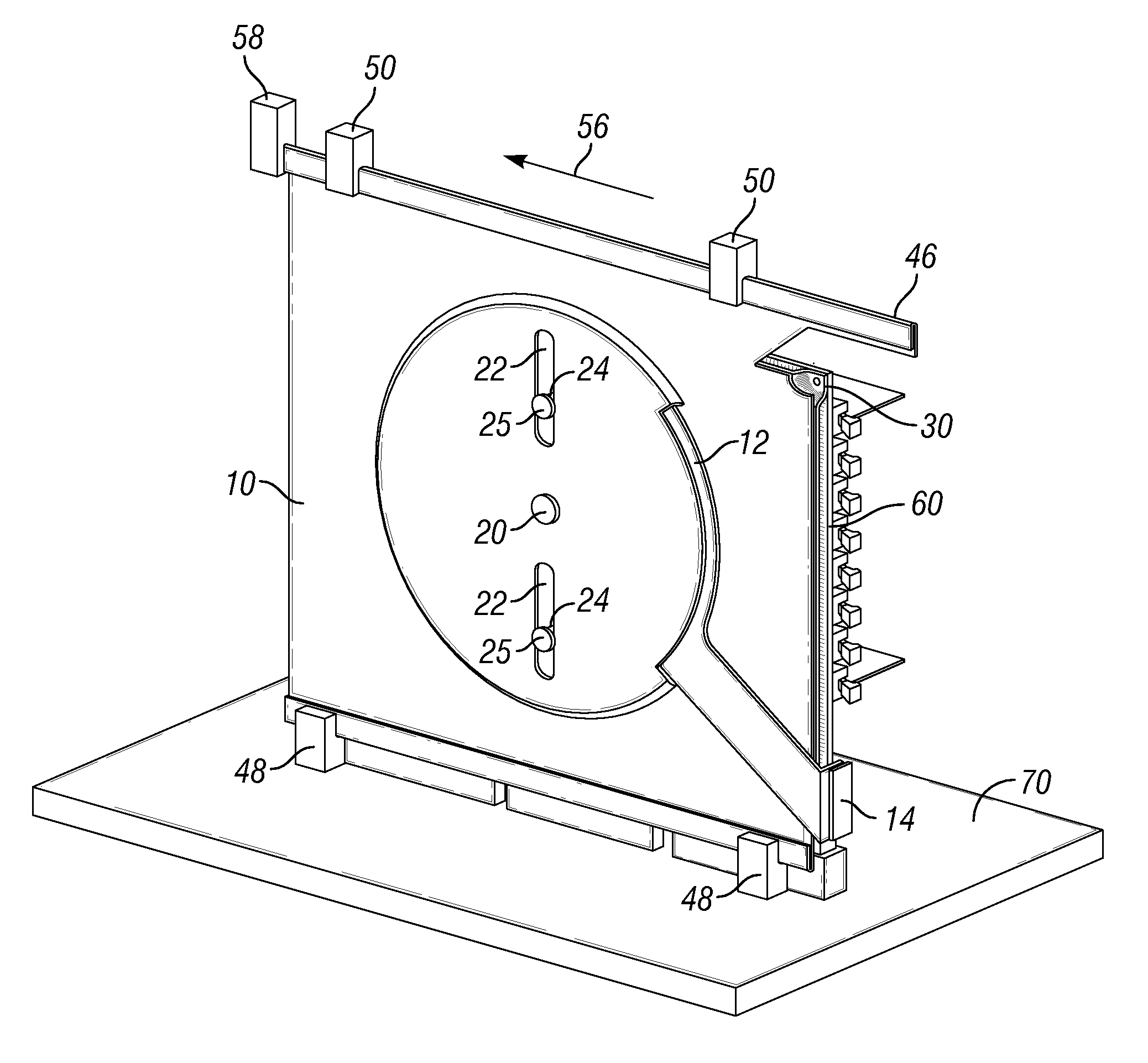
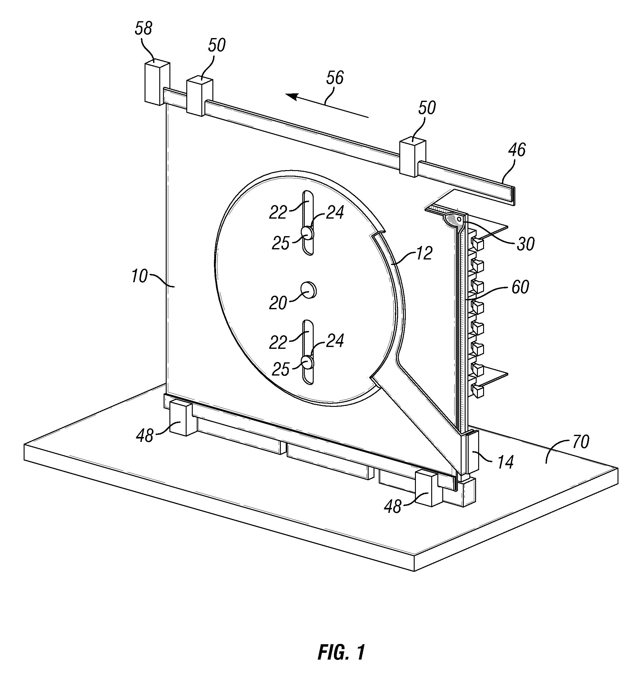
[0015]FIG. 1 is a perspective view of a guide plate 10 and a rotary linkage in accordance with one embodiment of the invention. The guide plate 10 is a rigid structural member that supports and positions other components. The guide plate 10 has a pivot coupling 20 that pivotally secures a rotatable plate 12 to the guide plate and a generally vertical slot 22 to accommodate the vertical movement of a pin 24 secured to a mounting plate 30. The pin 24 preferably terminates in a head (shown in FIG. 2) that prevents the pin 24 from pulling through the slot.

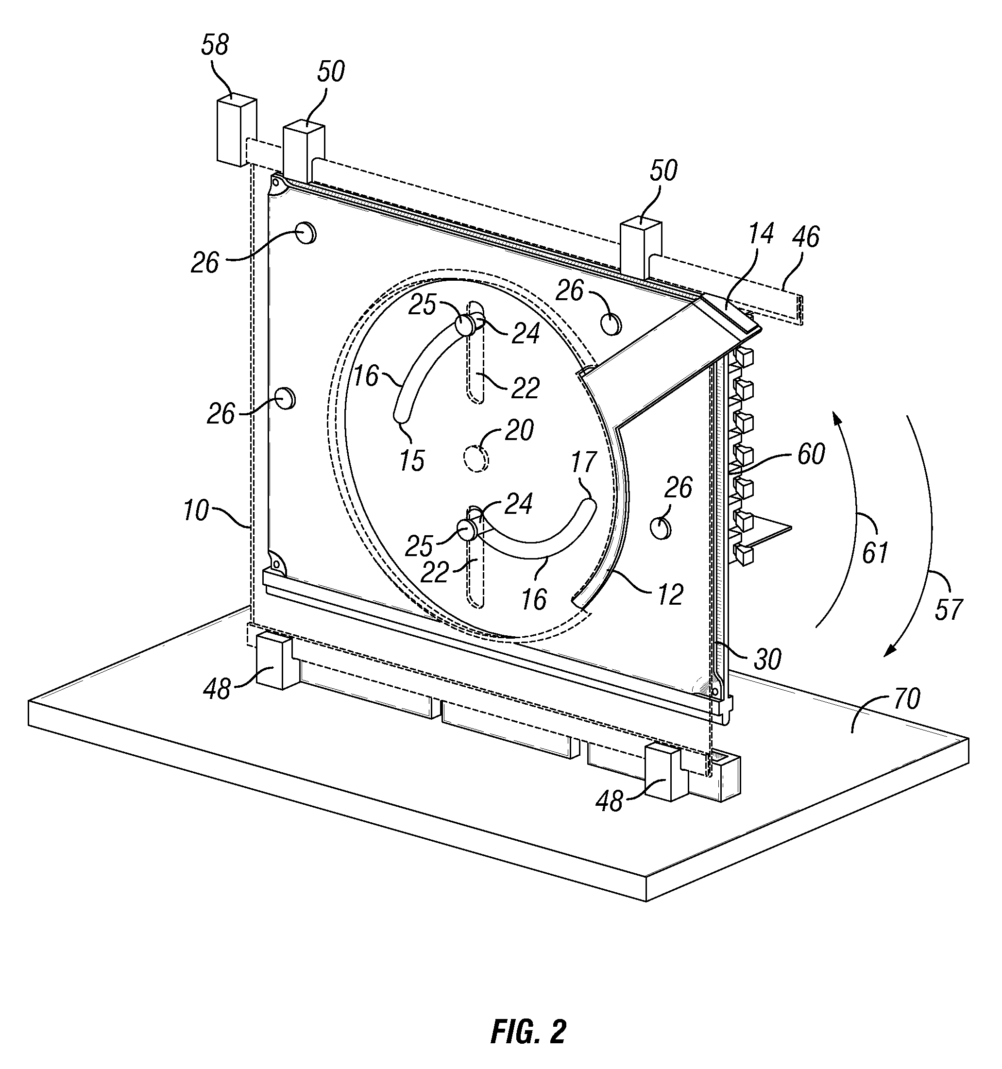
[0016]The rotary linkage allows for accurate and repeatable vertical movement of the mounting plate 30 relative to the guide plate 10 for insertion and removal from a connector where user access is constrained. Accordingly, the rotary linkage includes the rotatable plate 12 with a positioning handle 14 extending from one side for user access. The rotatable plate 12 is pivotally coupled to the guide plate 10 at the pivot coupling 20 and...


PUM

PropertyMeasurementUnit
distanceaaaaaaaaaa
rotationaaaaaaaaaa
mechanical advantageaaaaaaaaaa

Abstract

An apparatus comprising a guide plate selectively securable in a position adjacent a first electronic connector, wherein the guide plate includes a linear slot. A mounting plate is positioned generally parallel to the guide plate, wherein the mounting plate comprises two or more mounting pins, and is vertically slidably secured to the guide plate by the pins extending through the linear slot. Between the guide plate and the mounting plate, a rotatable plate is pivotally coupled, wherein the rotatable plate includes one or more cam slots slidably receiving a mounting pin. An electronic circuit board is coupled to the mounting plate, the electronic circuit board having a second electronic connector selectively mateable with the first electronic connector. The rotatable plate is actuated so that the cam slots cause the mounting plate and circuit board to move vertically to insert and remove the second connector relative to the first connector.

Description

BACKGROUND OF THE INVENTION[0001]1. Field of the Invention[0002]The present invention relates to printed circuit board installation in electronic devices. More specifically, the invention provides an apparatus for accurately docking a printed circuit board in a constrained space.[0003]2. Description of the Related Art[0004]Swappable components have become commonplace in computer systems. Computer systems often use swappable memory, hard drives, and various pieces of hardware commonly referred to as daughter cards. Many maintenance, repair, or upgrade operations involve the removal of a piece of hardware, or the insertion of a piece of hardware, or both while the computer is on and functioning.[0005]In a server rack, or chassis, many computer components are stored in close proximity. Often, these racks have numerous electronic circuit boards. The electronic circuit boards may be aligned in banks, both above or below, or beside each other. The electronic circuit boards may provide mem...

Claims


Application Information

Patent Timeline
Patent Type & Authority Patents(United States)
IPC IPC(8): H01R13/64
CPCH05K7/1402Y10T29/53252Y10T29/49126
Inventor DESROSIERS, NORMAN BRUCEHERRING, DEAN FREDERICK
Owner IBM CORP
Why Eureka
Try Eureka