Methods of forming fin field effect transistors using oxidation barrier layers

a field effect transistor and oxidation barrier technology, applied in the field of forming field effect transistors, can solve the problems of increasing cost and yield, and affecting the general semiconductor manufacturing of devices

Active Publication Date: 2007-11-20
SAMSUNG ELECTRONICS CO LTD
View PDF8 Cites 132 Cited by
  • Summary
  • Abstract
  • Description
  • Claims
  • Application Information

AI Technical Summary

Benefits of technology

[0025]In still other embodiments, oxidizing the fin structure to form the second curved sidewall portion may include oxidizing the fin structure for an increased duration as compared to oxidizing the fin structure to form the at least one curved sidewall portion.

Problems solved by technology

However, with increasing requirements for higher integration as well as higher performance, lower power dissipation, and greater economic efficiency, a variety of problems associated with degradation of transistor characteristics may arise.
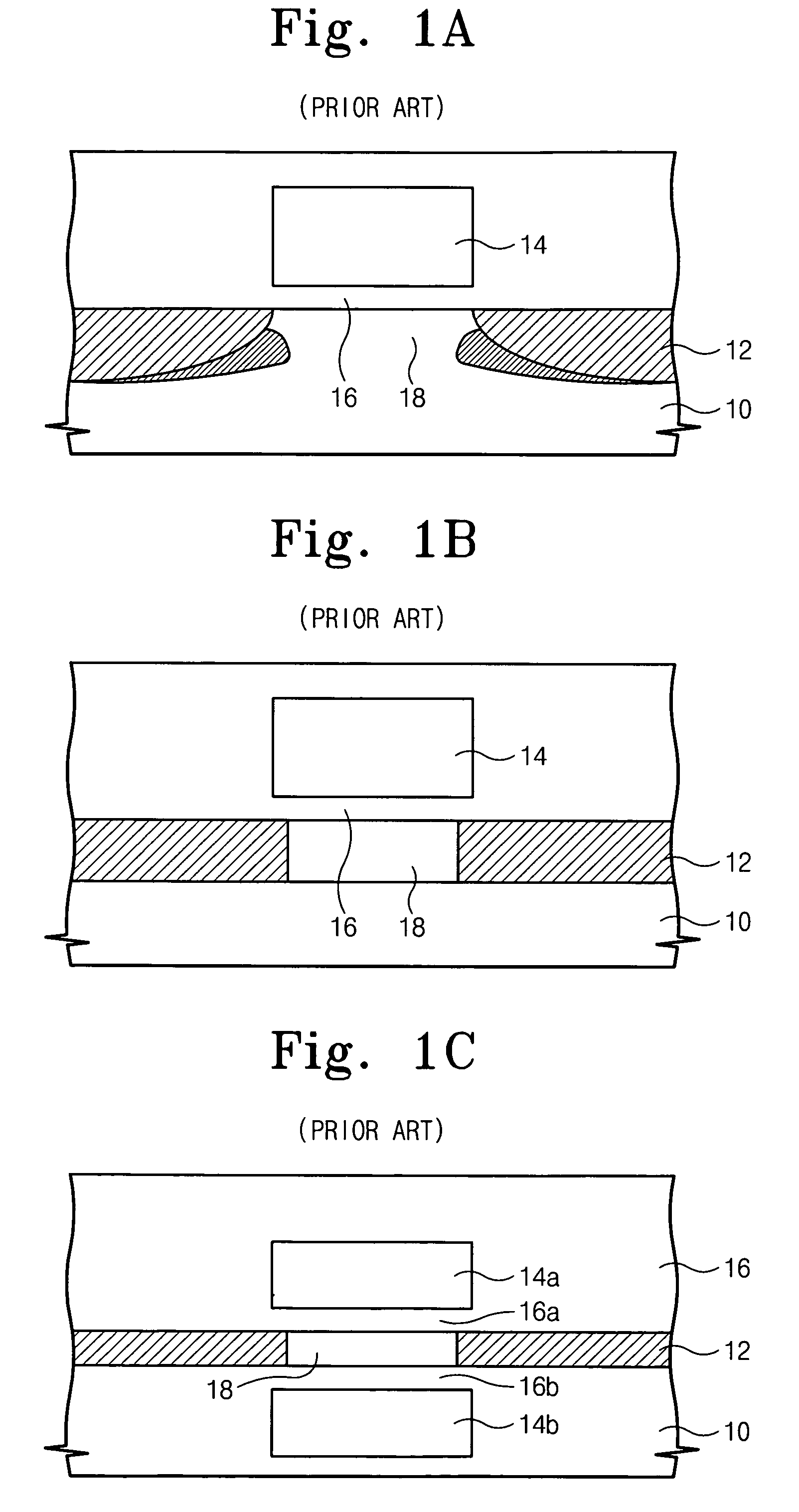
However, the devices of FIGS. 1B and 1C may require more complex fabrication techniques, which may increase cost and decrease yield.
Accordingly, such devices may be less practical in general semiconductor manufacturing.
For example, ultra-thin body transistors may be considerably more expensive to produce than conventional bulk-MOS devices.
Although they may provide improved performance in some areas, ultra-thin body transistors may be susceptible to floating body and heat transfer effects, and may have current limitations imposed by the body thickness.
However, double-gate devices may require a more complex fabrication processes, which may increase expense and lower yield.
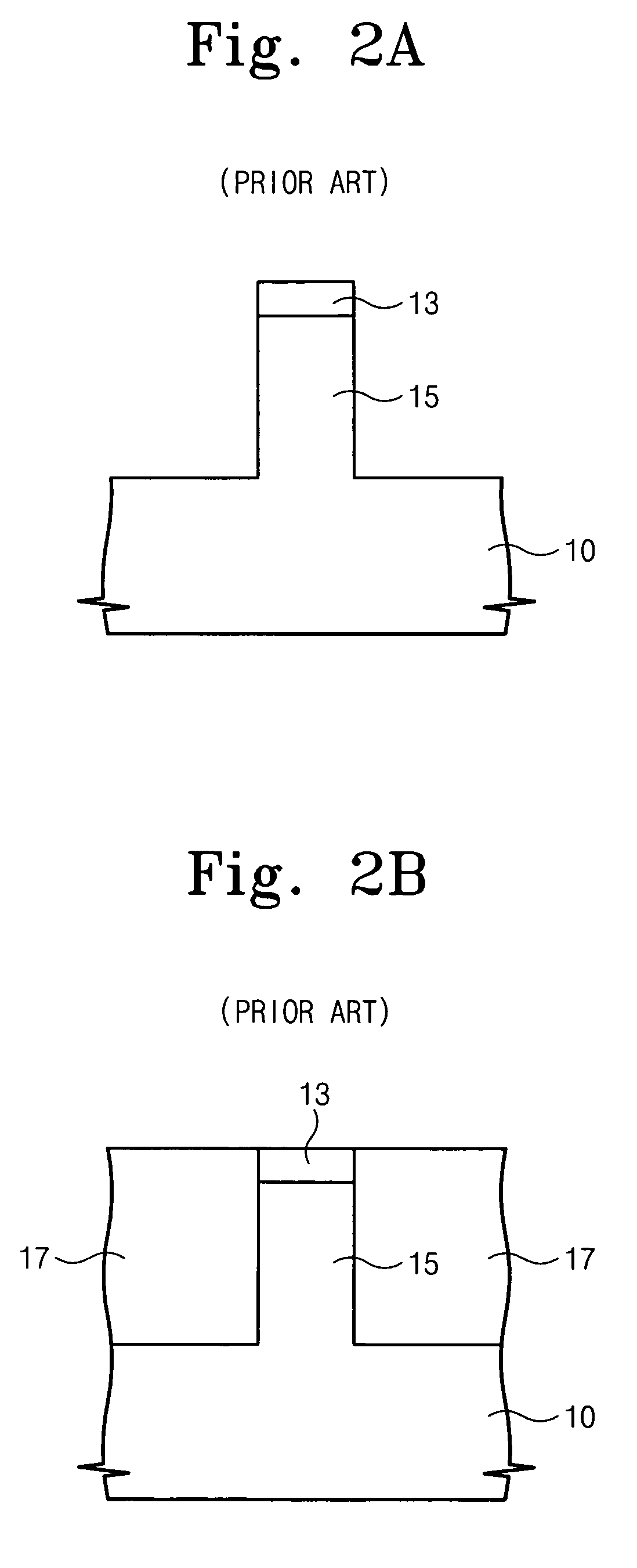
Accordingly, an under-cut region may be formed under the etch mask pattern 13, resulting in poor step coverage during subsequent processes, such as the deposition of gate electrode material.
However, a “hump” in subthreshold current may occur during operation of such a triple-gate FinFET.

Method used


Image

  • Methods of forming fin field effect transistors using oxidation barrier layers
  • Methods of forming fin field effect transistors using oxidation barrier layers
  • Methods of forming fin field effect transistors using oxidation barrier layers

Examples


Embodiment Construction

[0056]The present invention will be described more fully hereinafter with reference to the accompanying drawings, in which exemplary embodiments of the invention are shown. However, this invention should not be construed as limited to the embodiments set forth herein. Rather, these embodiments are provided so that this disclosure will be thorough and complete, and will fully convey the scope of the invention to those skilled in the art. In the drawings, the thickness of layers and regions are exaggerated for clarity. Like numbers refer to like elements throughout.

[0057]It will be understood that when an element such as a layer, region or substrate is referred to as being “on” or extending “onto” another element, it can be directly on or extend directly onto the other element or intervening elements may also be present. In contrast, when an element is referred to as being “directly on” or extending “directly onto” another element, there are no intervening elements present. It will al...


PUM


Abstract

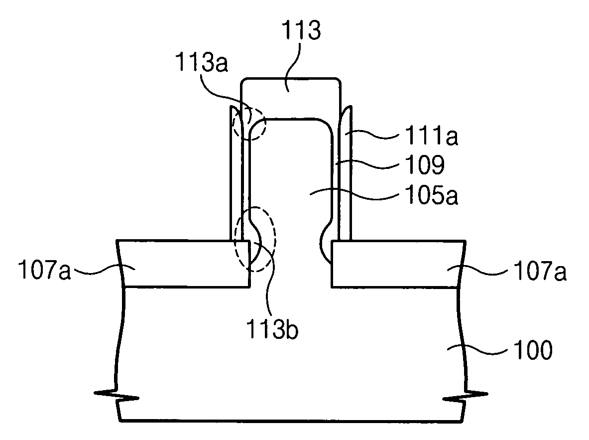
A method of forming a fin field effect transistor on a semiconductor substrate includes forming a fin-shaped active region vertically protruding from the substrate. An oxide layer is formed on a top surface and opposing sidewalls of the fin-shaped active region. An oxidation barrier layer is formed on the opposing sidewalls of the fin-shaped active region and is planarized to a height no greater than about a height of the oxide layer to form a fin structure. The fin structure is oxidized to form a capping oxide layer on the top surface of the fin-shaped active region and to form at least one curved sidewall portion proximate the top surface of the fin-shaped active region. The oxidation barrier layer has a height sufficient to reduce oxidation on the sidewalls of the fin-shaped active region about halfway between the top surface and a base of the fin-shaped active region. Related devices are also discussed.

Description

CLAIM OF PRIORITY[0001]This application claims priority from Korean Patent Application No. 2004-40986, filed on Jun. 4, 2004, the contents of which is hereby incorporated herein by reference in its entirety.FIELD OF THE INVENTION[0002]The present invention relates to semiconductor devices, and more specifically, to methods for forming field effect transistors (FETs) and related devices.BACKGROUND OF THE INVENTION[0003]Over the past 30 years, developments in silicon-based integrated circuit technology, such as metal-oxide-semiconductor (MOS) devices including field effect transistors (FETs and / or MOSFETs), have provided greater device speed, increased integration density, and improved device functionality with reduced cost. Referring to FIG. 1A, MOS devices are typically formed in a substrate 10 having heavily-doped source / drain (S / D) regions 12 separated by a more lightly-doped channel region 18. The channel region 18 may be controlled by a gate electrode 14 that is separated from t...

Claims


Application Information

Patent Timeline
Patent Type & Authority Patents(United States)
IPC IPC(8): H01L21/336H01L29/78H01L29/786
CPCH01L29/66553H01L29/66795H01L29/66545H01L29/78645B82Y10/00H01L29/7854H01L2029/7858
Inventor OH, CHANG-WOOPARK, DONG-GUNKIM, DONG-WONLEE, YONG-KYU
Owner SAMSUNG ELECTRONICS CO LTD
Why Eureka
Try Eureka