Methods of making optically clear structural laminates

a structural laminate and optically clear technology, applied in the field of structural laminates, can solve the problems of glass being too heavy, difficult to shape into complex forms, brittle and difficult to manufacture, etc., and achieves tensile strength of about 10,000 psi

Inactive Publication Date: 2007-12-04
THE BOEING CO
View PDF10 Cites 40 Cited by
  • Summary
  • Abstract
  • Description
  • Claims
  • Application Information

AI Technical Summary

Problems solved by technology

However, glass is also heavy, brittle and difficult to shape into complex forms.
These qualities make glass unsuitable for some applications.
Plastics, such as polycarbonate, are more resilient than glass, but they can only produce tensile strengths of about 10,000 psi.
Unfortunately, polymers may not possess the strength of glass.
Unfortunately, bond failures, or delaminations, at the interlayer interfaces have been noted.
Causes for bond failure may include mechanical or thermal stress, moisture ingress, and bond deterioration.
Although containment strength and resistance to delamination is increased, these materials may not be optically clear and may not be suitable for many applications.
Although increasing the amount of glass filler increases the strength of the transparent material, it is also said to considerably deteriorate the optical properties.
Further, these processes may not be suitable when using fabric fillers or unchopped fiber strand fillers.
The transmission decease was said to be due to the large number of interfaces where transmission losses occurred.
Unfortunately, these composites may be transparent only over a narrow temperature range and may not possess the strength needed for some applications.
Unfortunately, the described processes require several hours or days and the optical clarity of the resulting material is inadequate for some applications.
Additionally, these materials may have acceptable optical clarity only when the material is exposed to a narrow range of temperatures and they may be difficult to form into complex shapes.
Further, the manufacturing processes provided may not be desirable for many applications and may require secondary installation steps.
Unfortunately, optical transmission over still wider temperature ranges is needed.
Also, processes that require the careful arrangement of ribbon surfaces parallel to the surface of the polymer sheet may not be preferred when high volume laminate production is desired.
Additionally, because the composite sheets were laminated onto pre-formed polymer cores, these materials may not be preferred when complex component shapes are desired.
Also, the production of these materials may require high pressure.

Method used


Image

  • Methods of making optically clear structural laminates
  • Methods of making optically clear structural laminates
  • Methods of making optically clear structural laminates

Examples


example 1

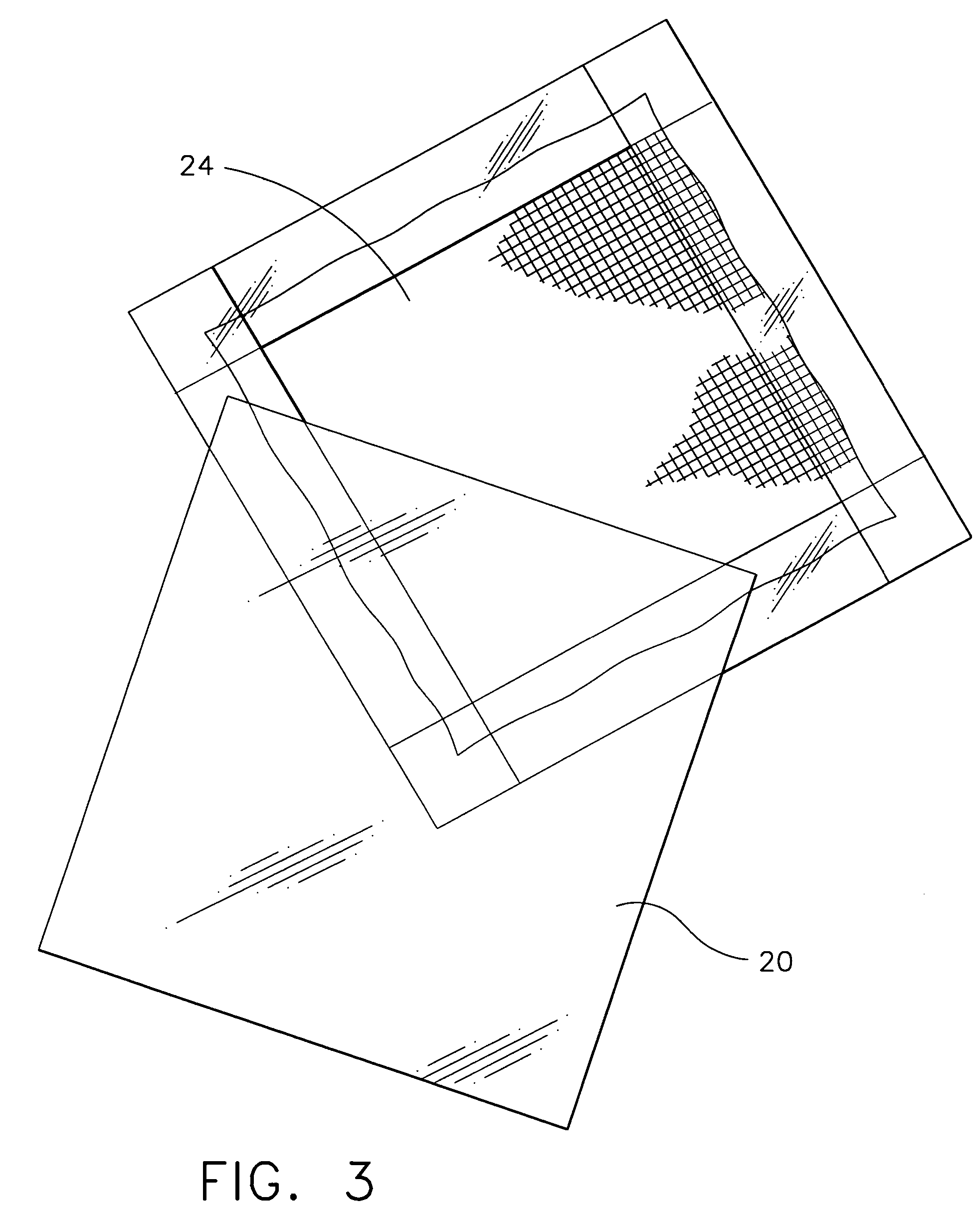
[0051]An optically clear structural laminate was produced according to an embodiment of the present invention. A fiberglass fabric 24, as seen in FIG. 3, was produced from the Hexcel Corporation in California. The fiberglass used was 108 style fabric 24 and was 0.0025″ thick. The fabric 24 had a refractive index of 1.550. The coupling agent was already applied to the fabric by the vendor. The coated fabric was then placed in the RTM mold. A 100 gram sample of ANGSTROMBOND AB9300 epoxy resin available from Fiber Optics Center in New Bedford, Mass. was degassed for 10 minutes in a bell jar using 28 inches of mercury and heated to a temperature of 150 degrees F. for 20 minutes. The polymer 23 had a refractive index of 1.548 at 589 nm. The heated polymer was then transferred to the mold by vacuum. The polymer impregnated fabric was then cured for 16 hours at 150 degrees F. and postcured at 250 degrees F. for 3 hours such that a laminate 20 was produced.

[0052]Other laminates 20 of the pr...


PUM

PropertyMeasurementUnit
refractive indexaaaaaaaaaa
temperatureaaaaaaaaaa

Abstract

An optically clear structural laminate includes a thermosetting resin, a silane coupling agent and a filler. The laminate has a high weight to strength ratio and is capable of optical transmission over a wide range of temperatures. The laminate has increased tensile strength and is capable of being easily formed into complex shaped components. The structural properties of the laminate make it useful as aircraft canopies and windows.

Description

STATEMENT OF RELATED APPLICATIONS[0001]This application is a divisional application of and claims priority from U.S. Ser. No. 10 / 259,702 filed Sep. 27, 2002, issued as U.S. Pat. No. 6,818,306.GOVERNMENT INTERESTS[0002]The invention was made with Government support under a contract awarded by Det 1 AFRL / PKN (−8100), Wright-Patterson AFB OH. The Government has certain rights in this invention.FIELD OF THE INVENTION[0003]The present invention generally relates to structural laminates and methods for producing the same. More specifically, this invention relates to optically clear structural laminates incorporating filler, such as fiberglass, and an optically clear resin matrix.BACKGROUND OF THE INVENTION[0004]Transparent materials have been widely used in a variety of articles, including glazing materials for buildings and vehicles, laboratory glassware, packaging, decorative lighting fixtures, safety panels at sports arenas, and architectural panels. Common transparent materials includ...

Claims


Application Information

Patent Timeline
Patent Type & Authority Patents(United States)
IPC IPC(8): B32B37/14C08K9/06C08L63/00B29C70/58B32B27/04B32B27/38B64C1/14
CPCB29C70/58B64C1/1484B32B27/00B29K2995/0026Y10T428/2971Y02T50/433Y10T428/24994Y10T428/31511Y10T428/31525Y02T50/40B32B2262/101B32B27/38B32B27/06B32B2260/021B32B2260/046
Inventor MILLER, MICHAEL C.KREY, TIMOTHY J.BRIDGES, DONALD J.MELQUIST, JAMES L.
Owner THE BOEING CO
Why Eureka
Try Eureka