Organic EL display luminance control method and luminance control circuit

a luminance control and luminance control technology, applied in static indicating devices, instruments, solid-state devices, etc., can solve the problem of easy over-control, and achieve the effect of increasing the luminance of the organic el display

Inactive Publication Date: 2007-12-04
PANASONIC INTELLECTUAL PROPERTY CORP OF AMERICA
View PDF21 Cites 12 Cited by
  • Summary
  • Abstract
  • Description
  • Claims
  • Application Information

AI Technical Summary

Benefits of technology

[0017]A luminance control method for an organic EL display according to the present invention is characterized by comprising a first step of calculating a luminance accumulation value for each screen on the basis of a video input signal; and a second step of controlling the amplitude of the video input signal on the basis of the luminance accumulation value calculated in the first step, and feeding to the organic EL display the video signal whose amplitude has been controlled and in that in the second step, the amplitude of the video input signal is controlled, when the luminance accumulation value calculated in the first step exceeds a predetermined value, such that the larger the difference between the luminance accumulated value and the predetermined value is, the smaller the amplitude of the video input signal becomes.
[0022]The gain calculation circuit has such input / output characteristics that a gain to be outputted is set to a constant value when the inputted luminance accumulation value is not more than a predetermined value, and the larger the inputted luminance accumulation value is, the smaller the gain to be outputted is made when the inputted luminance accumulation value exceeds the predetermined value, and the control circuit controls the white-side reference voltage such that the smaller the gain is, the lower the light-emitting luminance corresponding to the white level of the input signal becomes.
[0024]The gain calculation circuit has such input / output characteristics that a gain to be outputted is set to a constant value when the inputted luminance accumulation value is not more than a predetermined value, and the larger the inputted luminance accumulation value is, the smaller the gain to be outputted is made when the inputted luminance accumulation value exceeds the predetermined value, and the control circuit controls the white-side reference voltage such that the smaller the third gain is, the lower the light-emitting luminance corresponding to the white level of the input signal becomes.
[0026]The display luminance control means controls the display luminance of the organic EL display such that the display luminance of the organic EL display is reduced when the peripheral brightness judged by the judgment means is low, while being increased when the peripheral brightness judged by the judgment means is high.
[0029]The display luminance control means controls the display luminance of the organic EL display such that the display luminance of the organic EL display is increased when the display surface of the organic EL display is directed upward, while being reduced when the display surface of the organic EL display is directed downward.

Problems solved by technology

In the case of the feedback control, when the brightness of a video is rapidly changed, for example, excessive control easily occurs.

Method used


Image

  • Organic EL display luminance control method and luminance control circuit
  • Organic EL display luminance control method and luminance control circuit
  • Organic EL display luminance control method and luminance control circuit

Examples


first embodiment

[1] Description of First Embodiment

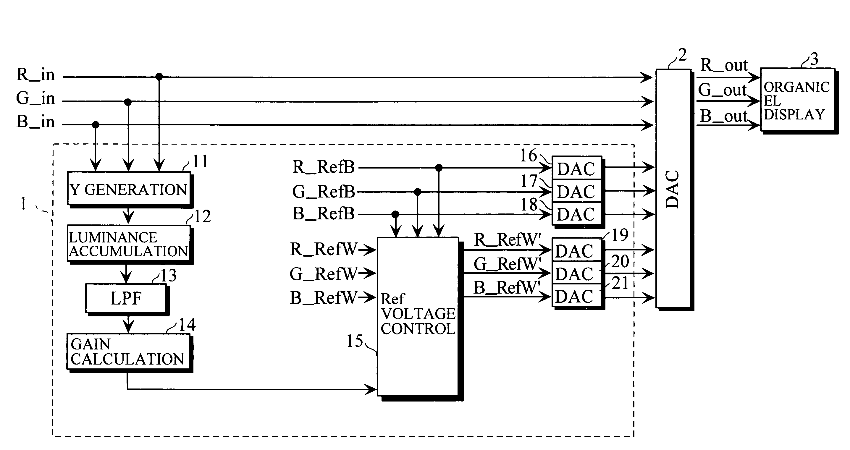
[0043]FIG. 3 illustrates the configuration of a luminance control circuit for an organic EL display according to a first embodiment of the present invention.

[0044]The luminance control circuit for the organic EL display comprises a reference voltage control circuit 1 and a DAC (Digital-to-Analog Converter) 2. Digital video input signals R_in, G_in, and B_in are fed to the reference voltage control circuit 1 and are fed to the DAC 2. The reference voltage control circuit 1 controls a reference voltage supplied to the DAC 2. The reference voltage supplied to the DAC 2 includes black-side reference voltages R_RefB, G_RefB, and B_RefB (generically referred to as a RefB) and white-side reference voltages R_RefW, G_RefW, and B_RefW (generically referred to as RefW), respectively, with respect to colors R (Red), G (Green), and B (Blue).

[0045]The black-side reference voltage RefB is a reference voltage for defining a light-emitting luminance corresponding ...

second embodiment

[2] Description of Second Embodiment

[0067]FIG. 7 illustrates the configuration of a luminance control circuit for an organic EL display according to a second embodiment of the present invention. In FIG. 7, the same components as those shown in FIG. 3 are assigned the same reference numerals and hence, the description thereof is not repeated.

[0068]The luminance control circuit for the organic EL display according to the second embodiment differs from the luminance control circuit for the organic EL display according to the first embodiment in the following points.

[0069](1) A multiplier 41 for controlling a luminance for the whole screen from the exterior is provided in a reference voltage control circuit 1.

[0070](2) Multipliers 51, 52, and 53 for allowing white balance control are provided in the reference voltage control circuit 1.

[0071](3) The characteristics of a light-emitting luminance corresponding to a display signal differ for colors R, G, and B, so that gain correction circu...

third embodiment

[3] Description of Third Embodiment

[0077]FIG. 9 illustrates the schematic configuration of a portable telephone set.

[0078]An MPU (Microprocessor Unit) 209 carries out the overall control of the portable telephone set. An antenna 201 transmits and receives electric waves. A transmitting / receiving unit 202 receives the electric waves, and transmits the contents of the receiving to the MPU 209. Further, the transmitting / receiving unit 202 transmits a transmission signal outputted from the MPU 209 with the transmission signal on the electric waves.

[0079]A microphone 203 feeds an audio signal to the MPU 209. A speaker 204 outputs as an audio the audio signal outputted from the MPU 209. A first camera 205 is a camera mounted on a front surface of the main body of the portable telephone set provided with an organic EL display 214, and sends to the MPU 209 a video which it has picked up. A second camera 206 is a camera mounted on a rear surface of the main body of the portable telephone set...


PUM


Abstract

A luminance control method for an organic EL display comprises a first step of calculating a luminance accumulation value for each screen on the basis of a video input signal, and a second step of controlling the amplitude of the video input signal on the basis of the luminance accumulation value calculated in the first step and feeding to the organic EL display the video signal whose amplitude has been controlled.

Description

[0001]This Application is a National Phase Application under 35 U.S.C. 371 claiming the benefit of PCT / JP02 / 13728 filed on Dec. 26, 2002, which has priority based on Japan Applications No. 2001-400238 filed on Dec. 28, 2001 and 2002-91976 filed on Mar. 28, 2002.TECHNICAL FIELD[0002]The present invention relates to a luminance control method and a luminance control circuit for an organic electroluminescence (EL) display and a portable telephone set comprising the organic EL display.BACKGROUND ART[0003]Examples of organic EL displays include passive-type ones having a simple matrix structure and active-type ones using a TFT (Thin Film Transistor).[0004]FIG. 1 illustrates the basic pixel structure of the active type organic EL display.[0005]A circuit corresponding to one pixel in the active type organic EL display comprises a switching TFT 101, a capacitor 102, a driving TFT 103, and an organic EL element 104.[0006]A display signal Data (Vin) is applied to the drain of the switching TF...

Claims


Application Information

Patent Timeline
Patent Type & Authority Patents(United States)
IPC IPC(8): G09G5/10G09G3/30H01L51/50G06F3/147G09G3/20G09G3/32G09G5/04H04B7/26
CPCG06F3/147G09G3/3208G09G5/04G09G2360/16G09G2320/0242G09G2330/021G09G2320/0238
Inventor MORI, YUKIOTANASE, SUSUMUYAMASHITA, ATSUHIROINOUE, MASUTAKAKINOSHITA, SHIGEOMURATA, HARUHIKO
Owner PANASONIC INTELLECTUAL PROPERTY CORP OF AMERICA
Why Eureka
Try Eureka