

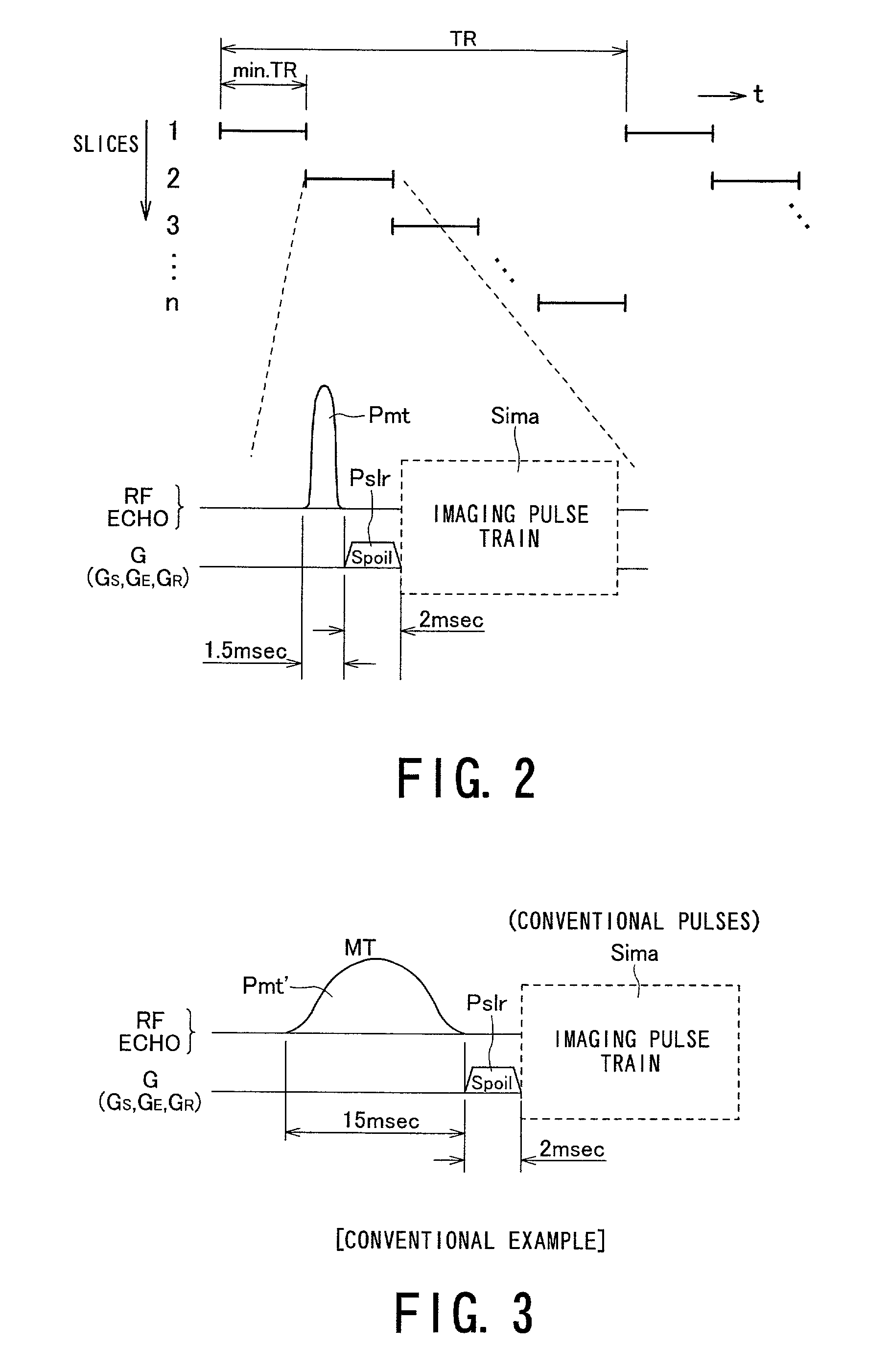
Magnetic resonance imaging using MT pulse of which duration is shorter
a magnetic resonance imaging and pulse technology, applied in the field of magnetic resonance imaging, can solve the problems of longer imaging time, and achieve the effect of shortening the scan time necessary
- Summary
- Abstract
- Description
- Claims
- Application Information
AI Technical Summary
Benefits of technology
Problems solved by technology
Method used
Image

Examples
first embodiment
[0041](First Embodiment)
[0042]Referring to FIGS. 1 to 9, a first embodiment of the present invention will now be described.
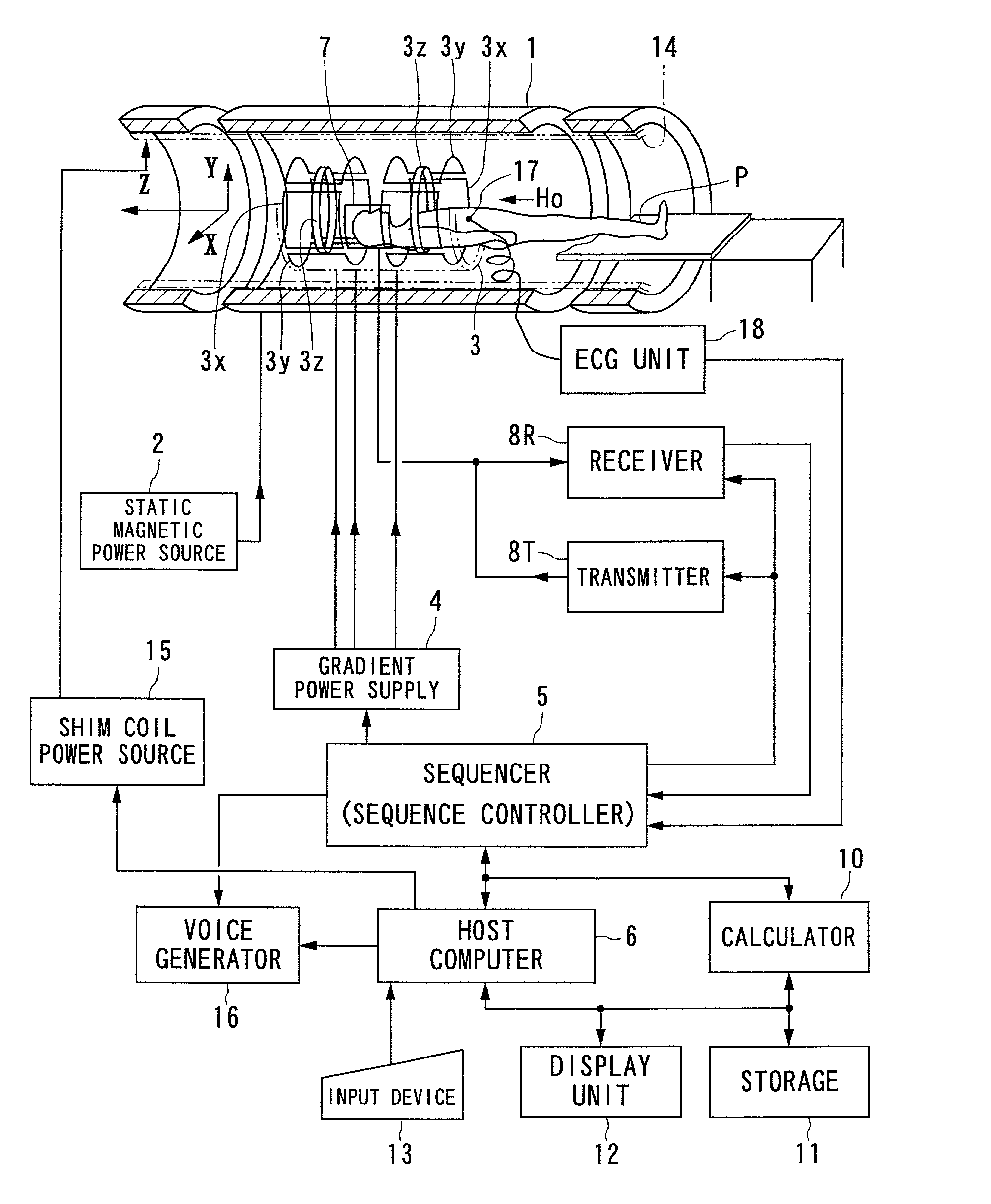
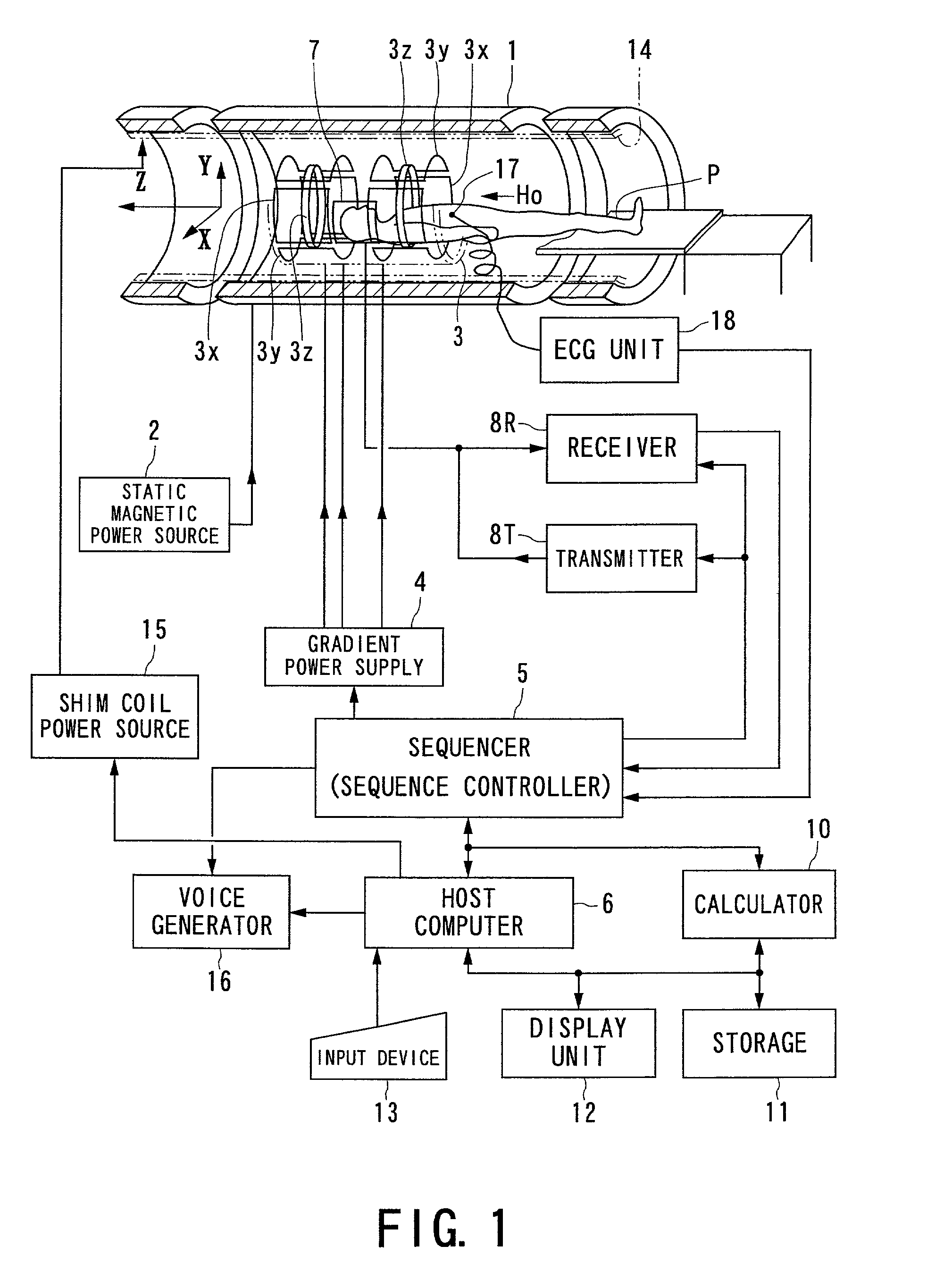
[0043]FIG. 1 a shows an outlined configuration of a magnetic resonance imaging (MRI) system in accordance with the first embodiment of the present invention.
[0044]The magnetic resonance imaging system comprises a patient couch on which a patient P as an object to be imaged lies down, static-field generating unit for generating a static magnetic field, magnetic-gradient generating unit for appending positional information to a static magnetic field, transmitting / receiving unit for transmitting and receiving a radio-frequency (RF) signal, controlling / calculating unit responsible for the control of the whole system and for image reconstruction, electrocardiographing unit for acquiring an ECG signal of the object P, and breath-hold instructing units for instructing the object to perform a temporary breath hold.
[0045]The static-field generating unit includes a magnet...
second embodiment
[0090](Second Embodiment)
[0091]Referring to FIGS. 10 and 11, a second embodiment according to the magnetic resonance imaging system of the present invention will now be described.
[0092]Instead of the two-dimensional scan with the use of the two-dimensional multislice technique, the second embodiment provides a magnetic resonance imaging system capable of imaging based on a three-dimensional scan technique as described for example in U.S. Pat. No. 5,627,468, to which the foregoing MT pulse is applied as well. This magnetic resonance imaging system is similar in the hardware configuration to that of the first embodiment, so its detailed explanation will be omitted.
[0093]In the magnetic resonance imaging system, under the control of the sequencer 5, a pulse sequence shown in FIG. 10 is conducted by way of example for the three-dimensional scan.
[0094]As understood from the figure, the pulse sequence includes an MT pulse Pmt applied first together with a slice magnetic gradient GS, which...
PUM
 Abstract
Description
Claims
Application Information