Fluorescent material, scintillator using same, and radiation detector using same

a fluorescence material and scintillator technology, applied in the direction of conversion screens, optical radiation measurement, nuclear engineering, etc., can solve the problems of reducing the use efficiency of x-rays, vibration from the exterior vibrating the electrode plate, and high internal pressure of the xenon gas filled chamber, so as to reduce the afterglow level, shorten the scan time, and improve the effect of resolution

Active Publication Date: 2012-03-06
HITACHI METALS LTD
View PDF12 Cites 6 Cited by
  • Summary
  • Abstract
  • Description
  • Claims
  • Application Information

AI Technical Summary

Benefits of technology

[0061]A fluorescent material according to the present invention is able to provide a scintillator having a low level of afterglow 1 to 300 ms after the termination of X-ray radiation, as compared with a conventional fluorescent material of GGAG:Ce. A radiation detector according to the present invention, formed using such a fluorescent material as a scintillator, has a shorter scan time. The detector may contribute thereby to increased resolution. The detector may also have stable detection performance.

Problems solved by technology

However, the interior pressure of the xenon gas filled chamber is high.
This decreases use efficiency of X-rays.
However, if the electrode plate is thin, vibration from the exterior vibrates the electrode plate.
This generates noise.
This constitutes a problem.
This causes noise in a silicon photodiode.
This in turn decreases the sensitivity.
However, an increase in the thickness thereof hinders miniaturization of an X-ray detecting element.
This increases the cost.
All this causes an X-ray detecting element to have a shortened integration time.

Method used


Image

  • Fluorescent material, scintillator using same, and radiation detector using same
  • Fluorescent material, scintillator using same, and radiation detector using same
  • Fluorescent material, scintillator using same, and radiation detector using same

Examples


first embodiment

[0086]A fluorescent material according to the first embodiment of the present invention contains Ce as an fluorescent activator. In addition, the material contains at least Gd, Al, Ga, O and Si. The element M is at least one of Mg, Ti, and Ni. The composition of the material is expressed by the following general formula.

(Gd1−x−zLuxCez)3+a(Al1−u−sGauSc5)5−aO12

wherein

[0087]0≦a≦0.15,

[0088]0≦x≦0.5,

[0089]0.0003≦z≦0.0167,

[0090]0.2≦u≦0.6, and

[0091]0≦s≦0.1,

and wherein,

[0092]0.5≦Si concentration (mass ppm)≦10, and

[0093]0≦M concentration (mass ppm)≦50.

[0094]This material according to the present invention must contain Si. The content of Si ranges from 0.5 to 10 mass ppm. FIG. 4 shows that when the content of Si exceeds 10 mass ppm, this causes the 3 ms afterglow to exceed 800 ppm. Therefore, the after glow exceeds the tolerance level. This causes the upper limit of the content of Si to be set at 10 mass ppm. However, the upper limit is preferably 5 mass ppm. In addition, first, the raw mater...

second embodiment

[0127]The second embodiment will be described below.

[0128]The above fluorescent material is used as a scintillator. The second embodiment relates to a radiation detector having this scintillator and a light receiving element. This element is designed to detect fluorescent light emitted from the scintillator. This radiation detector is preferably mounted in a medical observation device or a medical inspection device such as an X-ray CT (Computed Tomography) scanner, a PET (Positron Emission Tomography) scanner, or a PET / CT scanner.

[0129]The reason for the above is as follows.

[0130]If the above fluorescent material is used as a scintillator, this makes the fluorescence intensity high. In addition, this makes the decay time constant small. In addition, this makes the level of afterglow low. This makes it possible to obtain a high-performance radiation detector having high time resolution.

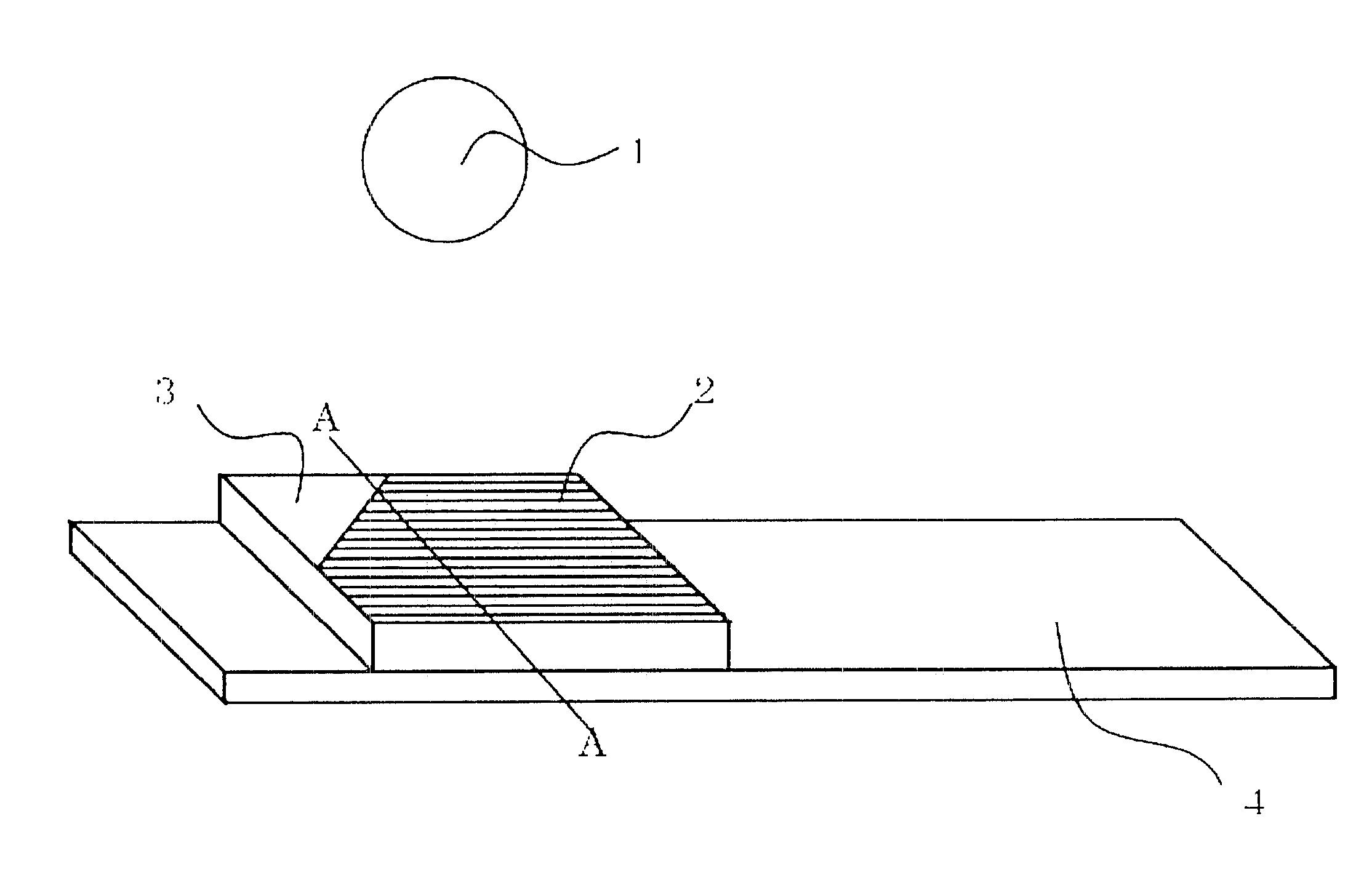
[0131]As shown in FIGS. 15 and 16, this radiation detector may be designed to include a scintillato...

example 1

[0136]A resin pot having a volume of 1 liter was provided. An amount of 200 g of a raw material, 1300 g of a high-purity alumina ball having a diameter of 5 mm, and 200 cc of ethanol were placed into the pot. After mixing the contents for 12 h, change in the mass of the alumina ball is 0.06 g. In view of this, and considering that Al2O3 from the ball of a ball mill will enter into the mixture, 126. 91 g of Gd2O3 (Si: 3 mass ppm), 0.363 g of CeO2, 40.62 g of Al2O3 (Si: 10 mass ppm), and 32.05 g of Ga2O3 (Si: 10.0 mass ppm) were weighed. Regarding a powder made of a Gd2O3 raw material, a powder having an average particle size of 2 μm was used. The average particle size refers conventionally an average value. However, in this case, exceptionally, the average particle size means a median particle diameter. Regarding a powder made of an Al2O3, raw material, a powder having an average particle size of 0.6 μm was used. Regarding a powder made of a Ga2O3, raw material, a powder having an av...


PUM


Abstract

Problem:The problem is to provide a fluorescent material for a scintillator to be used in a radiation detector. In view of this, the fluorescent material must have a high fluorescent intensity and a low level of afterglow 1 to 300 ms after the termination of X-ray radiation.Solution:The above problem is solved in that the above fluorescent material contains Ce as an activator. In addition, the material contain at least Gd, Al, Ga, O, Si, and a component M. The component M is at least one of Mg, Ti, and Ni. In addition, the composition of the material must be expressed by the general formula:(Gd1−x−zLuxCez)3+a(Al1−u−sGauScs)5−aO12 wherein 0≦a≦0.15, 0≦x≦0.5, 0.0003≦z≦0.0167, 0.2≦u≦0.6, and 0≦s≦0.1, and wherein, regarding the concentrations of Si and M, 0.5≦Si concentration (mass ppm)≦10, and 0≦M concentration (mass ppm)≦50.

Description

TECHNICAL FIELD[0001]The present invention relates to a fluorescent material configured to absorb radiation such as X-rays and emit fluorescence. The present invention also relates to a scintillator using such a fluorescent material. The present invention also relates to a radiation detector using such a fluorescent material.BACKGROUND ART[0002]One example of an X-ray diagnostic device is an X-ray CT (Computed Tomography) scanner. This CT scanner is composed of an X-ray tube and an X-ray detector. The tube is designed to emit a fan-shaped beam of X-rays, i.e., an X-ray fan beam. The detector is composed of many X-ray detecting elements arrayed side-by-side. The scanner operates as follows: The X-ray tube emits a series of X-ray fan beams one after another onto the X-ray detector. Each time a fan beam is incident on the surface a tomographic layer, it is oriented at a predetermined angle, for example, 1 degree, from the previous one. The scanner collects thereby data on absorptions o...

Claims


Application Information

Patent Timeline
Patent Type & Authority Patents(United States)
IPC IPC(8): G01T1/20G01J1/58
CPCC09K11/7774C01F17/0025C01G15/006C04B35/44C04B35/6455G21K4/00C04B2235/77C01P2002/50C01P2002/54C01P2002/84C01P2006/12C04B2235/3217C04B2235/3224C04B2235/3229C04B2235/3286C04B2235/5409C04B2235/5436C04B2235/5445C04B2235/604C04B2235/6585C04B2235/661C04B2235/728C04B2235/764C01F17/34
Inventor NAKAMURA, RYOUHEIUEDA, SHUNSUKE
Owner HITACHI METALS LTD
Why Eureka
Try Eureka