Skin impedance matched biopotential electrode

a biopotential electrode and skin impedance technology, applied in the field of sensing voltage potentials, can solve the problems of lower level of electrolytic contact noise, achieve the effect of reducing the imbalancing effect of skin rs and contact rc resistance, high input impedance and low output impedan

Inactive Publication Date: 2005-08-11
ADVANCED BIOELECTRIC CORP
View PDF8 Cites 86 Cited by
  • Summary
  • Abstract
  • Description
  • Claims
  • Application Information

AI Technical Summary

Benefits of technology

[0063] up with a with both of a fifth A dual-pickup, common noise rejection canceling circuit is based upon the differential comparison of two separately detected body signals. To be fully effective, a common mode noise rejection circuit should have balanced input connections on each input channel. By employing high Re and Ra values, the imbalancing effects of variable skin Rs and contact Rc resistances are reduced. Accordingly, it is a preferred embodiment of the invention that two pickup electrodes, each incorporating an electrode interface as stipulated above, provide signals to a differential amplifier that has a grounded return coupled to the body and provides an output signal that has been obtained from the two pickup electrodes with common mode noise rejection.
[0064] Due to the fact that noise can arise through the leads coupling the electrode to a signal display apparatus (“whip” noise), it is preferable that the electrode be an “active” electrode that is provided with high input impedance circuitry, approximately located at the electrode, and which may serve to provide a low output impedance to the cables extending to the display apparatus. Ideally, this circuitry can be in the form of on-board electrical components that are supported within the same structure as the electrode. Such “onboard” circuitry provides a high input impedance buffer circuit which serves as an impedance converter. Power for this circuitry can be supplied in DC format through the same connecting cable that delivers to the display apparatus the signal that corresponds to the actual sensed signal. Alternately, an internal battery or other types of power sources can provide power.

Problems solved by technology

This gives rise to a lower level of electrolytic contact noise.

Method used


Image

  • Skin impedance matched biopotential electrode
  • Skin impedance matched biopotential electrode
  • Skin impedance matched biopotential electrode

Examples


Embodiment Construction

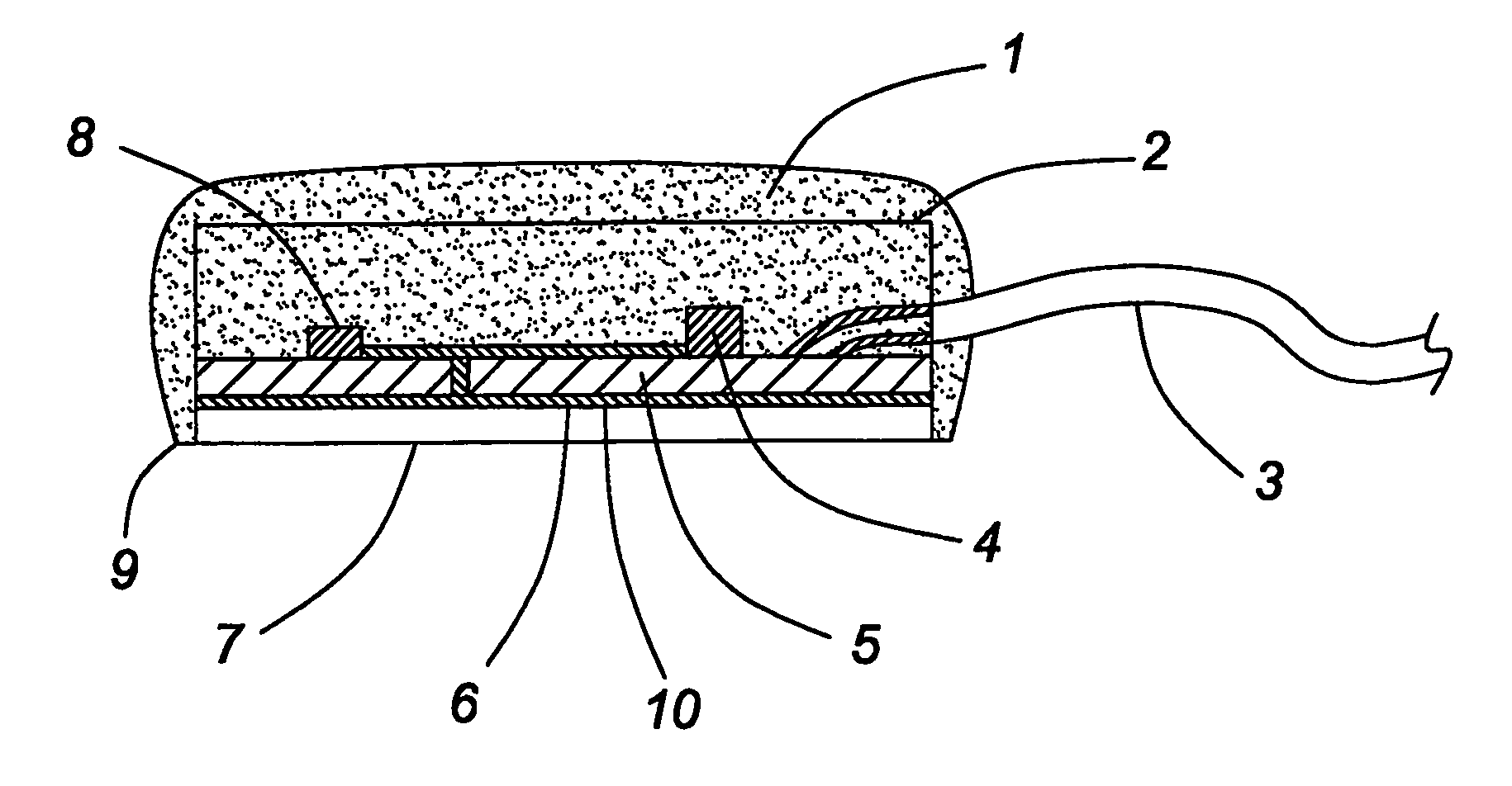
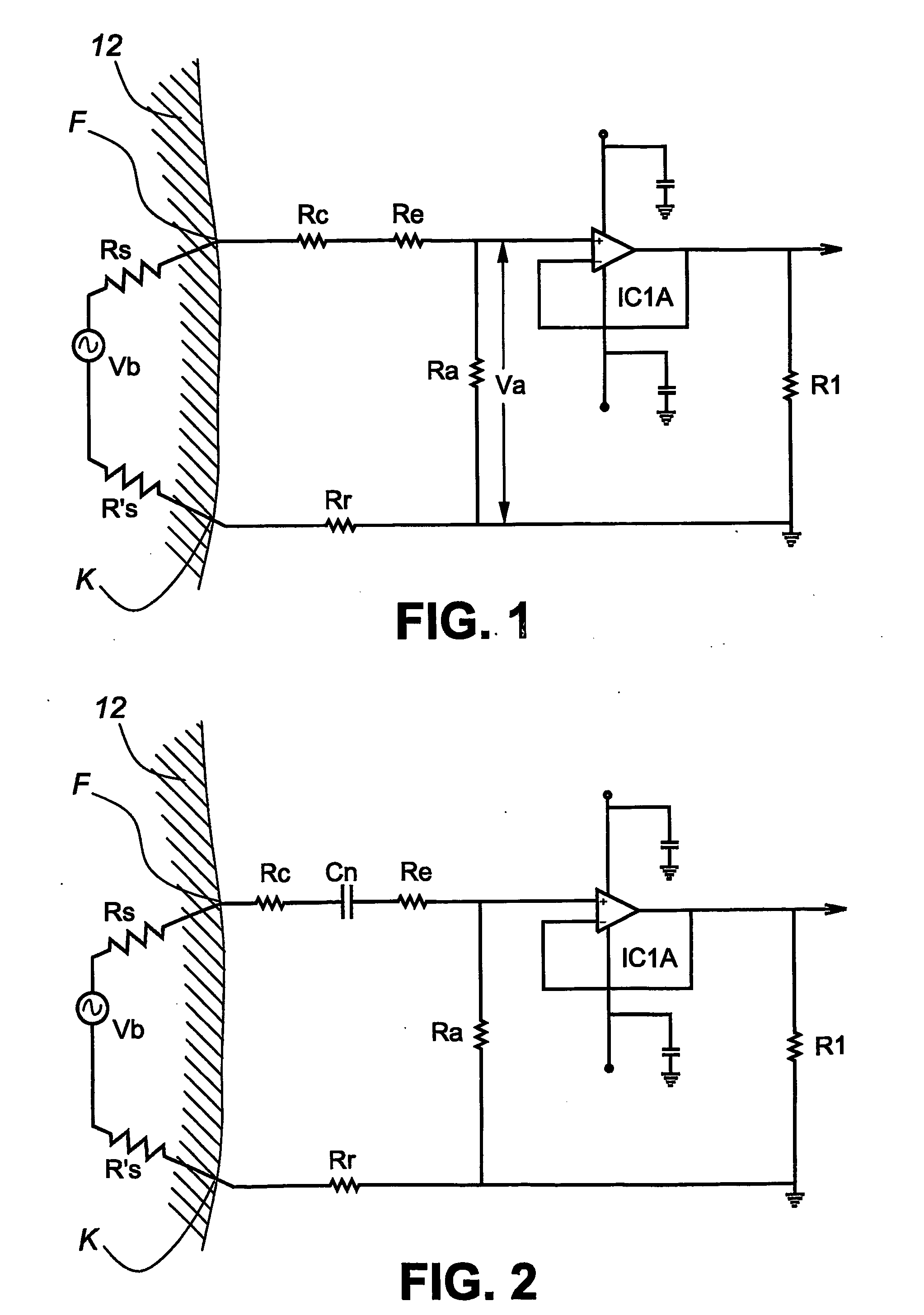
[0079]FIG. 1 depicts a pictorial schematic layout for the electrical circuit of the invention, when analyzed in terms of DC currents, before taking into consideration polarization noise effects.

[0080] All pickup electrodes are used to convey signals originating inside a body 12 to an external reading device such as an ECG machine or heart rate counter through a closed circuit which provides a voltage divider network. The electrical signal inside the body can be called the body-source, as represented by a voltage Vb. Analyzing this circuit for its DC characteristics, the body source, along with the voltage divider required for the pickup of the bio-signal is illustrated in FIG. 1 wherein: [0081] Rs and R's are the skin resistance; [0082] F is the location of the body-to-electrode interface; [0083] Rc is the contact resistance at the interface F; [0084] Re is the electrode bulk resistance, and [0085] Ra is the resistance across which the output signal Va is measured.

[0086] The end o...


PUM


Abstract

A bio-electrode for detecting heart signals and the like comprises a dry electode surface having an elevated resistivity to reduce the effect of polarization noise. The electrode is combined with a circuit having an external discharge resistor across which an output signal is obtained wherein the discharge resistor has a value which reduces the time constant of polarization noise to less than one second.

Description

FIELD OF THE INVENTION [0001] This invention relates to the field of sensing voltage potentials arising from within a living body. More particularly, it relates to electrocardiogram-ECG electrodes for detecting heart signals and other body-originating potential signals such as for monitoring heart rate and cardiac pacemaker activity. BACKGROUND TO THE INVENTION [0002] Electrodes for detecting electrical signals arising from within a living body may be classed, amongst other characteristics, as either wet- or dry-type electrodes. Wet-type electrodes operate on the basis of the presence of an electrolytic layer formed at the interface between electrode and the body surface that his provided as part of the electrode or as part of the standard electrode application process. Dry-type electrodes are intended to operate without the intentional addition of such an electrolytic layer but sometimes may require a natural layer of sweat or other fluids to function. It is noted that contemporary...

Claims


Application Information

Patent Timeline
Patent Type & Authority Applications(United States)
IPC IPC(8): A61B5/308
CPCA61B5/04284A61B5/302A61B5/308A61B5/305A61B5/28
Inventor KOLPIN, HANSBATKIN, IZMAILDEL RE, RICCARDO BRUN
Owner ADVANCED BIOELECTRIC CORP
Why Eureka
Try Eureka