Multi-channel output DC-DC inverter

A DC converter and multi-output technology, which is applied in the direction of output power conversion device, conversion equipment with intermediate conversion to AC, conversion of DC power input to DC power output, etc., can solve the difficult and soft switching and rectification loss of topological circuits Large size, high cost, etc., to achieve the effect of easy implementation, enhanced EMC performance, and improved efficiency

Active Publication Date: 2006-11-29
EMERSON NETWORK POWER CO LTD
View PDF0 Cites 16 Cited by
  • Summary
  • Abstract
  • Description
  • Claims
  • Application Information

AI Technical Summary

Problems solved by technology

But this topology circuit is difficult to achieve soft switching
Since there is no soft switch, the switching loss of the switching tube is large, and the rectifier tube needs to use a diode with a higher withstand voltage and a larger on-state voltage drop, and the rectification loss is large, so the efficiency of this topology circuit is low.
In addition, because there is no soft switching, the di / dt of the switch tube is poor, the reverse recovery current of the diode is large, and the electromagnetic compatibility (EMC) is poor
In addition, the dual-transistor forward multi-output converter uses output inductors, and the cost is relatively high

Method used


Image

  • Multi-channel output DC-DC inverter
  • Multi-channel output DC-DC inverter
  • Multi-channel output DC-DC inverter

Examples


specific Embodiment approach 1

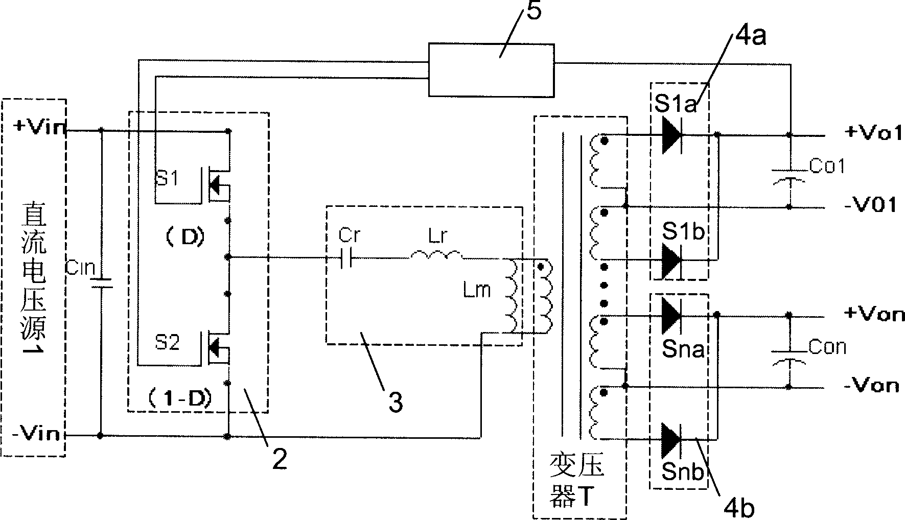
[0034] like figure 2 As shown, a multi-output DC-DC converter includes a chopper 2 , a resonant circuit 3 , a transformer T, a main rectifier circuit 4 a , an auxiliary rectifier circuit 4 b , and a PWM control circuit 5 .

[0035] The input end of the chopper 2 is connected to the output end of the DC voltage source 1 .

[0036] The PWM control circuit 5 outputs a square wave with a duty ratio of D, a switching frequency of fs, and a square wave with a duty ratio of 1-D to the chopper 2, respectively. The PWM control circuit 5 includes a drive circuit, a PWM modulation circuit, an isolation circuit, a PID (proportional, integral, differential control) regulator, and a reference voltage circuit.

[0037] The chopper 2 is composed of a first switch tube S1 and a second switch tube S2 in series, the chopper 2 is connected in parallel with the above-mentioned DC voltage source 1, and the PWM control circuit outputs a square wave with a duty ratio of D to the first switch tube ...

specific Embodiment approach 2

[0088] like Image 6 As shown, the difference between this specific embodiment and the specific embodiment 1 is that the resonant capacitor Cr is directly connected to the transformer T and the DC voltage source-Vin terminal.

specific Embodiment approach 3

[0089] like Figure 7 As shown, the difference between this specific embodiment and the specific embodiment 1 is that the resonant capacitor Cr is directly connected to the transformer T and the first resonant inductor Lr.


PUM


Abstract

This invention discloses a multi-channel output DC-DC converter including a transformer, a primary an a sub-commutation circuits, a PWM control circuit, in which, a secondary winding output of the transformer is connected with the inputs of the primary and the sub-commutation circuits, a chopper is composed of a first and a second switch tubes in series, the PWM control circuit outputs pulses with the duty ratio of D and 1-D to the control end of the two switch tubes to fix up the dead time of them, a resonance loop is composed of a resonance capacitor, a first and a second resonance inductors parallel to the first winding of the transformer, the input of the loop is connected with the chopper, the first inductor resonates with the capacitor to shut up the quasi-zero current of the two tubes and the second, the first inductor resonate with the capacitor to turn on the zero voltage of the two switch tubes.

Description

technical field [0001] The invention relates to a DC-DC converter, in particular to a multi-channel output DC-DC converter. Background technique [0002] In modern electronic equipment, multiple DC voltage sources of different levels are usually required for power supply. If a single output power supply is used for each level of DC voltage, although the power supply requirements of the load can be well met, the cost, volume and weight of the power supply will increase. Therefore, a multi-output DC-DC converter is generally used to provide multiple DC voltage sources of different levels. [0003] like figure 1 As shown, among the existing multi-output DC-DC converters, the dual-tube forward multi-output DC-DC converter is widely used. But this topology circuit is difficult to realize soft switching. Since there is no soft switch, the switching loss of the switching tube is large, and the rectifier tube needs to use a diode with a higher withstand voltage and a larger on-s...

Claims


Application Information

Patent Timeline
Patent Type & Authority Applications(China)
IPC IPC(8): H02M3/28H02M3/335H02M3/338
Inventor 雷兴华
Owner EMERSON NETWORK POWER CO LTD
Why Eureka
Try Eureka