MRI system and MR imaging method

a magnetic resonance imaging and imaging method technology, applied in the field of magnetic resonance imaging, can solve the problems of inability to inject contrast medium into patients, high patient mental and physical burden, and high examination cost of contrast mr angiography

Inactive Publication Date: 2012-10-16
TOSHIBA MEDICAL SYST CORP
View PDF36 Cites 7 Cited by
  • Summary
  • Abstract
  • Description
  • Claims
  • Application Information

AI Technical Summary

Benefits of technology

[0013]The present invention has been made to break through the foregoing current situations. A first object of the present invention is to, therefore, provide an MR imaging technique for producing high-quality blood flow images in a shorter scan time, without using a contrast medium.
[0014]A second object of the present invention is to provide an MR imaging technique, in addition to the above first object, which is capable of obtaining different types of blood flow images from echo data acquired by the same scanning, thus enriching pieces of information to be provided about blood flows.
[0016]A fourth object of the present invention is to depict such slower-speed flows as peripheral blood flows in a shorter period of time in a steady and high-quality manner, with no contrast medium injected.
[0021]This provides higher-quality blood flow images in a shorter scan time, without injection of a contrast medium. Moreover, from echo data acquired in the same imaging, blood flow images such as an arterial phase image and a venous phase image, which are different in types, can be produced in a simple manner. It is therefore possible to enrich blood flow information that can be provided through one time of imaging.
[0024]Since an applied direction of the readout gradient pulse is almost made to agree with a flowing direction of blood and a dephasing or rephasing pulse is added to the readout gradient pulse, a slower-speed flow, such as blood flows in an inferior limb, can be depicted with accuracy, without using a contrast medium. Particularly, a high-quality image in which arteries and veins are visually separated can be depicted within a short period of time.

Problems solved by technology

However, this contrast MR angiography needs an invasive treatment to inject the contrast medium.
First of all, mental and physical burdens on patients become large.
Second, examination cost of the contrast MR angiography is still expensive.
Third, there are some cases where a contrast medium cannot be injected into patients due to patient's physical characteristics.
However, when the TOF technique or phase contrast technique is used for obtaining MR images of a patient's pulmonary field or abdomen which depict flows of large vessels, such as the aorta, in their superior-inferior directions, it is required to scan slices located vertically to the flowing direction.
Thus, in the case that two-dimensional slice imaging is performed to acquire such axial images, it is impossible to obtain an image in which blood flows are directly reflected.
Three-dimensional image data spatially containing blood flows are therefore needed, but the number of slices increases which will cause an entire imaging time to be longer.
One drawback is that a longer scan time is still needed in total, because a three-dimensional scan should be performed two times. Another is that registration may be mistaken if the position of a patient's body moves between two times of scans, which is apt to deteriorate quality of blood flow images which will be produced by the subtraction.
Additionally, there may occur influence of positional shifts due to heartbeats, it was almost impossible to detect such slower-speed fluid flows by the conventional techniques.

Method used


Image

  • MRI system and MR imaging method
  • MRI system and MR imaging method
  • MRI system and MR imaging method

Examples


first embodiment

[0053](1) First Embodiment

[0054]Refereeing to FIGS. 1 to 14, a first embodiment will now be described.

[0055](1.1) Configuration of System

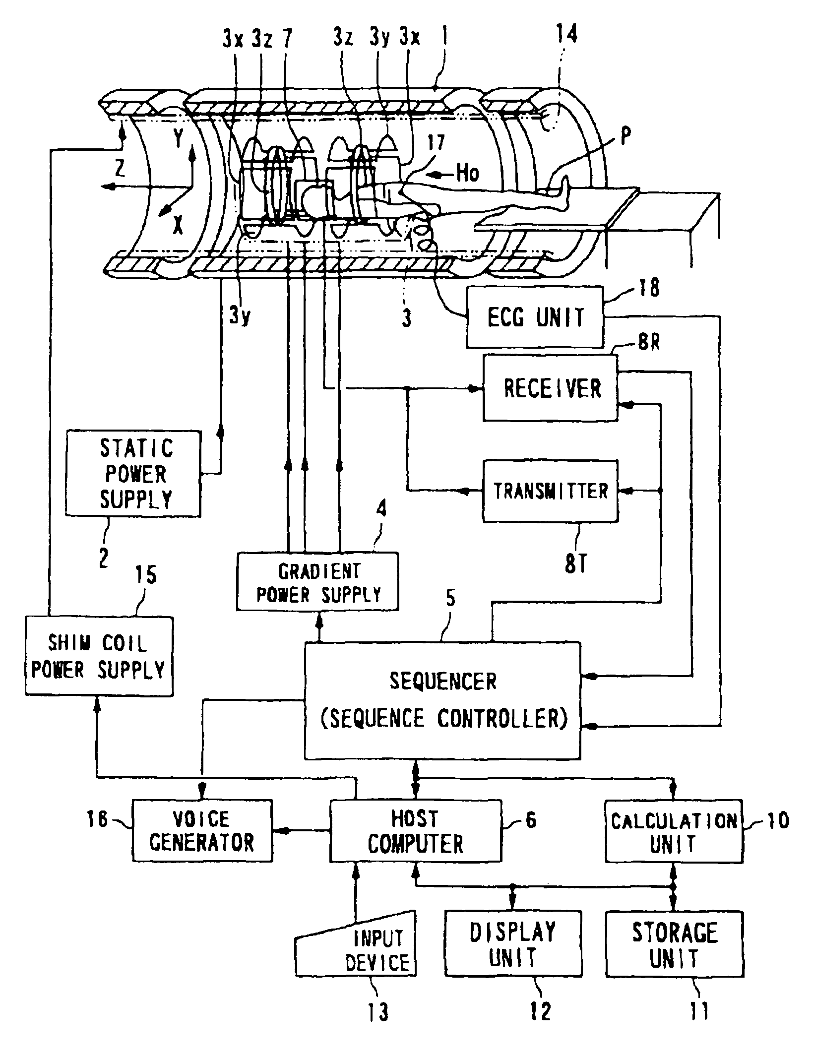
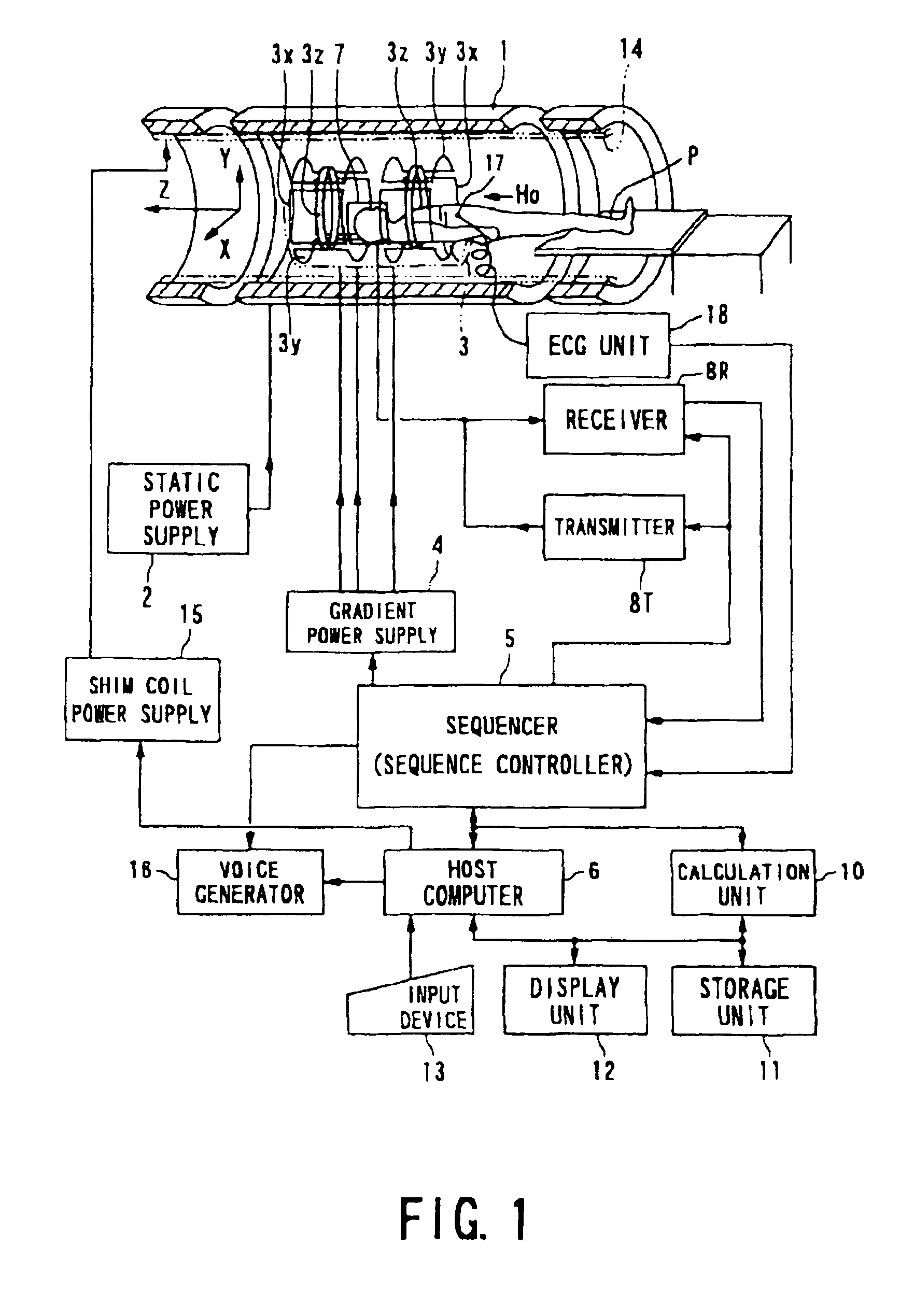
[0056]FIG. 1 shows an outlined hardware configuration of an MRI (magnetic resonance imaging) system used in common in each of the following embodiments.

[0057]The MRI system comprises a patient couch on which a patient P lies down, static magnetic field generating components for generating a static magnetic field, magnetic field gradient generating components for appending positional information to a static magnetic field, transmitting / receiving components for transmitting and receiving radio-frequency signals, control and operation components responsible for controlling the whole system and reconstructing images, and electrocardiogram components for acquiring an ECG signal of a patient, the ECG signal being employed as a signal indicative of cardiac time phases of the patient.

[0058]The static magnetic field generating components include a magnet 1 ...

second embodiment

[0139](2) Second Embodiment

[0140]Referring to the foregoing drawings and FIGS. 15 to 22, a second embodiment of the present invention will now be described.

[0141]MR imaging according to the second embodiment is characterized in that a dephasing or rephasing pulse is added to the read-out gradient pulse GR in order to depict slow-speed blood flow such as blood flow in the inferior limb. The present embodiment uses an MRI system that is the same or identical in both hardware configuration and ECG-prep scan as or to those in the first embodiment.

[0142](2.1) Imaging Scan

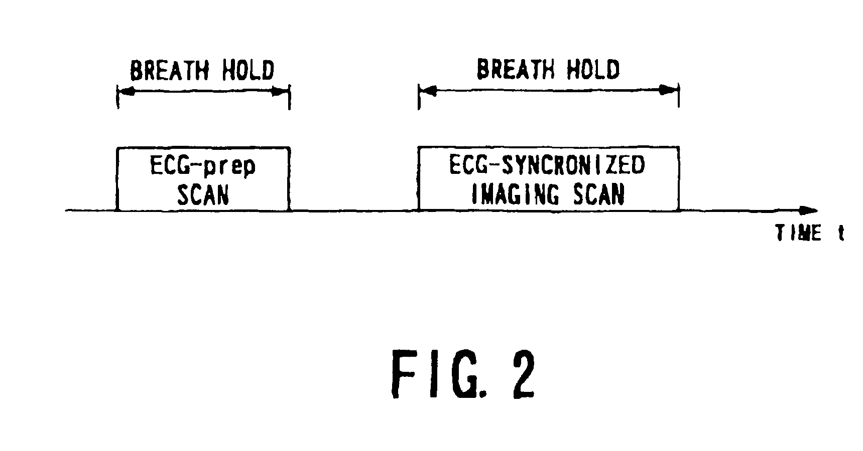
[0143]In the present embodiment, as shown in FIG. 15, the ECG-prep scan is followed by two times of imaging scans each performed on the ECG-synchronized technique by which the two synchronization timings are used, respectively.

[0144]Referring to FIGS. 16 to 20, operations of the imaging scans of two times (namely, imaging of two times) will now be described. The host computer 6 executes a not-shown given main program, du...

third embodiment

[0197](Third Embodiment)

[0198]Referring to the foregoing figures and FIGS. 24 to 26, a third embodiment of the present invention will now be described. An MRI system used in this embodiment is configured in hardware in the same or similar way as or to the first and second embodiments.

[0199]In the third embodiment, the first-time and two-time imaging scans, that is, two times of imaging scans which have been conducted in the second embodiment are conducted as one-time imaging scan. In this scan, the foregoing dephasing and rephasing pulses are used according to the systole and diastole in each cardiac cycle.

[0200]The artery and vein in the inferior limb will now be employed as fluid of a slower speed and an artery / vein visually separated image thereof will now be obtained. Similarly to the sequence shown in FIG. 2, the ECG-prep scan is first performed, and then a one-time imaging scan is performed using the ECG-synchronized technique. The ECG-prep scan is conducted as described in th...


PUM


Abstract

An ECG-prep scan is used to set an optimum time phase in both systole and diastole of the heart. At each of the different time phases, an imaging scan is started to acquire a plurality of sets of echo data. An artery / vein visually separated blood flow image is produced from the echo data. The imaging scan uses a half-Fourier technique, for example. This provides high-quality blood flow images with shorter scan time, without injecting a contrast medium. Additionally, with a readout gradient pulse applied substantially parallel with a direction of slowly flowing blood, a scan is performed in synchronism with an optimally determined cardiac time phase. The readout gradient pulse has a dephasing pulse for enhancing differences in a flow void effect depending on blood flow velocities. This enables slow-speed flows, such as blood flows in the inferior limb, to be depicted without fail.

Description

BACKGROUND OF THE INVENTION[0001]1. Field of the Invention[0002]The present invention relates to magnetic resonance imaging (MRI) for internally imaging an object to be examined on the basis of a magnetic resonance phenomenon of nuclear spins of the object, particularly, to an MRI (magnetic resonance imaging) system and an MR (magnetic resonance) method capable of acquiring artery / vein visually separated images of the object without using a contrast medium.[0003]2. Description of the Related Art[0004]Magnetic resonance imaging is based on an imaging technique for magnetically exciting nuclear spins of an object located in a static magnetic field by applying a radio-frequency (RF) signal of a Larmor frequency and reconstructing an image from MR signals induced by the excitation.[0005]For clinically obtaining blood flow images of the pulmonary field or abdomen of a patient by magnetic resonance imaging, MR angiography has been put in practical use, in which a contrast medium is inject...

Claims


Application Information

Patent Timeline
Patent Type & Authority Patents(United States)
IPC IPC(8): A61B5/055G01R33/32G01R33/48G06T1/00
CPCA61B5/0263A61B5/055A61B5/7257A61B5/7289A61B5/7207A61B6/541
Inventor MIYAZAKI, MITSUESUGIURA, SATOSHI
Owner TOSHIBA MEDICAL SYST CORP
Why Eureka
Try Eureka