Connection of the hitch arm of a pull-type crop harvesting machine to a tractor

a technology of crop harvesting machine and hitch arm, which is applied in the direction of harvesters, applications, agriculture tools and machines, etc., can solve the problems of reducing manoeuverability, poorer drive transmission efficiency than mechanical systems, and requiring a high power requirement, so as to reduce or eliminate the flexing of hoses

Active Publication Date: 2007-12-18
MACDON INDS
View PDF5 Cites 26 Cited by
  • Summary
  • Abstract
  • Description
  • Claims
  • Application Information

AI Technical Summary

Benefits of technology

[0028]a third pivot coupling connecting the hitch arm to the second coupling member which allows pivotal movement of the hitch arm relative to the second coupling member about an upright axis which is generally upright so as to allow side to side movement of the header relative to the hitch connector and the tractor;
[0040]Preferably the hoses flex to accommodate the side to side movement of the header. However as an alternative, there may be provided live couplings which provide a swivel joint at which the side to side movement is accommodated, thus reducing or eliminating the flexing of hoses.

Problems solved by technology

A drive with a high power requirement is not typically better suited to be hydraulic.
In fact it would often be better suited for the drive to be mechanical, as hydraulic drive would generally result in poorer drive transmission efficiencies than mechanical systems.
This arrangement has however a number of disadvantages in that different designs are provided for the draw bar construction and for the three-point hitch construction and of course it is highly desirable that a common design is provided.
Furthermore the arrangement locates the pump at a forward position which reduces the length of the connecting shaft which can be connected between the pump and the PTO shaft which thus reduces manoeuverability.
This construction provides a complex device for towing equipment in a row one behind the other which has achieved no commercial success.

Method used


Image

  • Connection of the hitch arm of a pull-type crop harvesting machine to a tractor
  • Connection of the hitch arm of a pull-type crop harvesting machine to a tractor
  • Connection of the hitch arm of a pull-type crop harvesting machine to a tractor

Examples


Embodiment Construction

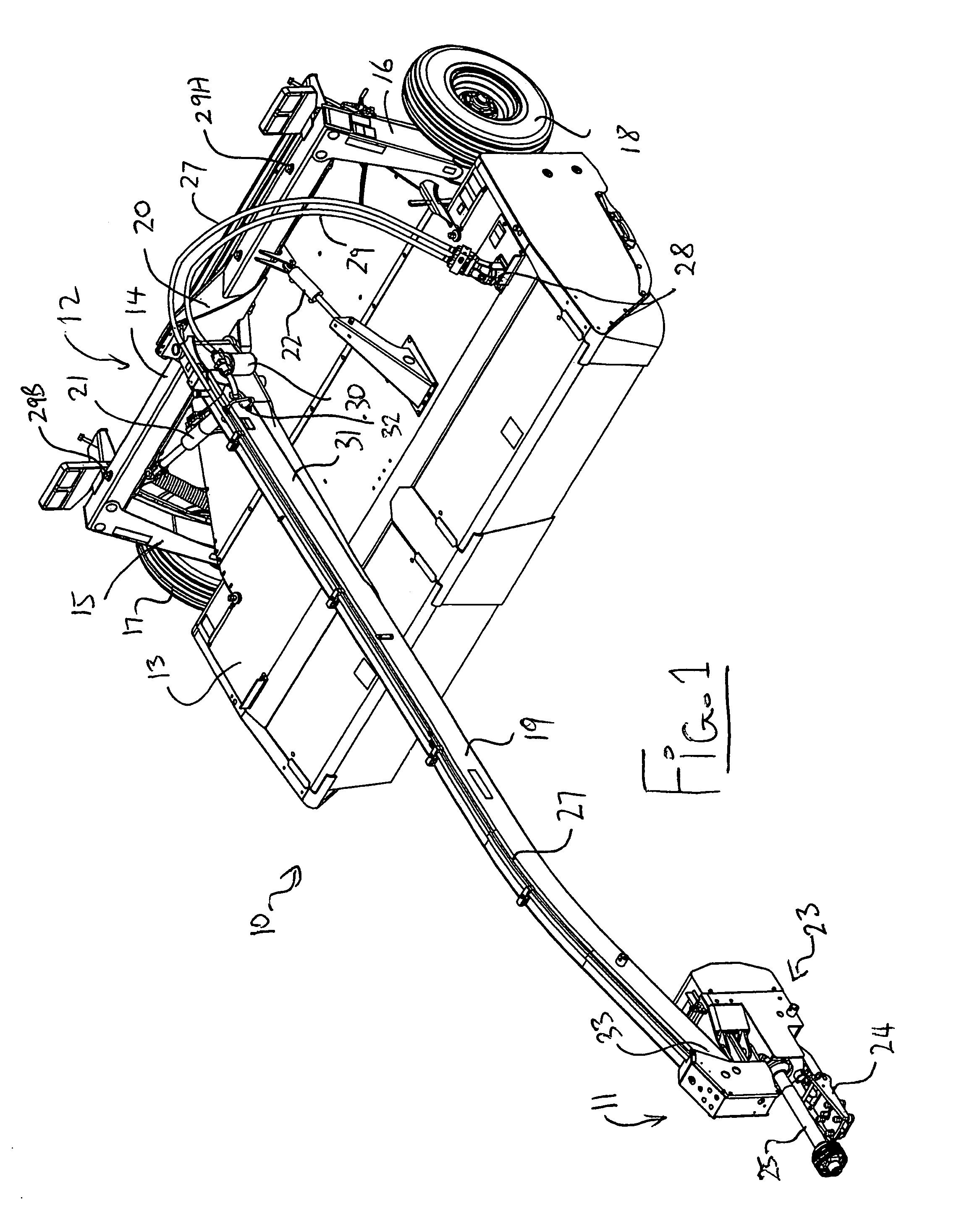
[0078]In FIG. 1 is shown a pull type harvesting machine generally indicated at 10 for attachment to a tractor (not shown) by a hitch coupling generally indicated at 11. The crop harvesting machine shown is of the type which uses a row of discs mounted on a cutter bar as shown in FIG. 6. Thus each disc is mounted on the cutter bar for rotation about its own axis with the axes spaced positions across the width of the cutter bar and when the axes generally vertical. The discs carry blades at 180° spacing of the discs so that the disc rotate 90° out of phase with the next adjacent disc thus allowing the cutting action of the blades to overlap. Arrangements of this type are well known and many examples can be found in the prior art. The cutter bar of FIG. 6 is mounted on a frame generally indicated at 12 and is covered by a housing generally indicated at 13 so that the cutter system is enclosed for safety.

[0079]The frame 12 includes a transverse beam 14 which extends across the width of ...


PUM


Abstract

A pull-type crop harvesting machine has a header carried on a frame mounted on ground wheels with a hitch arm extending from the frame over the header to a hitch connector of a tractor. The hitch arm is mounted for pivotal movement about a generally upright axis such that in a first position the tractor tows the frame in echelon to one side and in a second position the tractor tows the frame in echelon. There is provided connecting assembly for connecting the forward end of the hitch arm to a hitch connector of the tractor and a mechanical connection from the PTO of the tractor to a pump for hydraulically driving the cutting assembly. The connecting assembly provides three axes of pivotal movement for up and down, tilting and side to side movement of the header relative to the tractor. These axes are defined by pivot couplings which are stacked so that the forward end of the hitch arm extends over the connecting assembly and the pump so that the mechanical connection to the pump passes underneath forward end of the hitch arm.

Description

[0001]This invention relates to a pull-type crop harvesting machine of the type including a header carried on a frame to be towed behind a tractor and particularly to a connection between the hitch arm and the tractor, which includes a pivotal towing connection and a mechanical drive connection for providing power to a pump of a hydraulic drive of the machine.BACKGROUND OF THE INVENTION[0002]Pull type harvesting machines are towed from the tractor by a hitch arm which requires to be adjusted in angle relative to the frame of the machine for fine steering movements and more coarse movement to the transport position.[0003]Some machines are required to follow the tractor only to one side and thus include a hitch arm which is located at one end of the machine. In others in which the present invention is particularly effective, the hitch arm to the tractor extends from the frame over the header to a hitch coupling and can be swung by an operating cylinder from one side of the header to t...

Claims


Application Information

Patent Timeline
Patent Type & Authority Patents(United States)
IPC IPC(8): A01B59/06A01B59/043A01B63/02A01B63/118
CPCA01B71/066
Inventor BARNETT, NEIL GORDON
Owner MACDON INDS
Why Eureka
Try Eureka