Loaded antenna

a technology of loaded antennas and antenna supports, applied in the field of telecommunications, can solve the problem that none of these antenna configurations provides a multiband behaviour

Inactive Publication Date: 2007-12-25
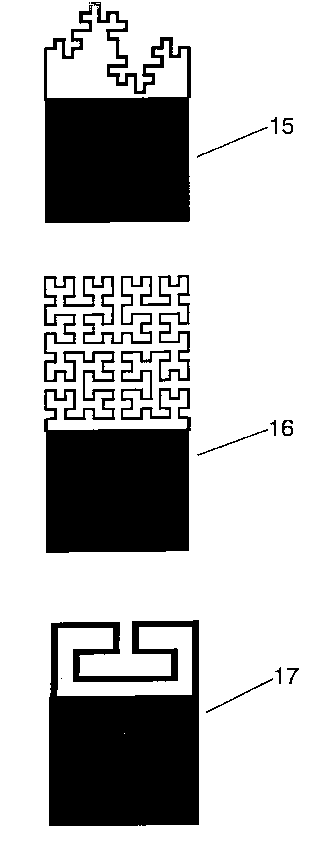
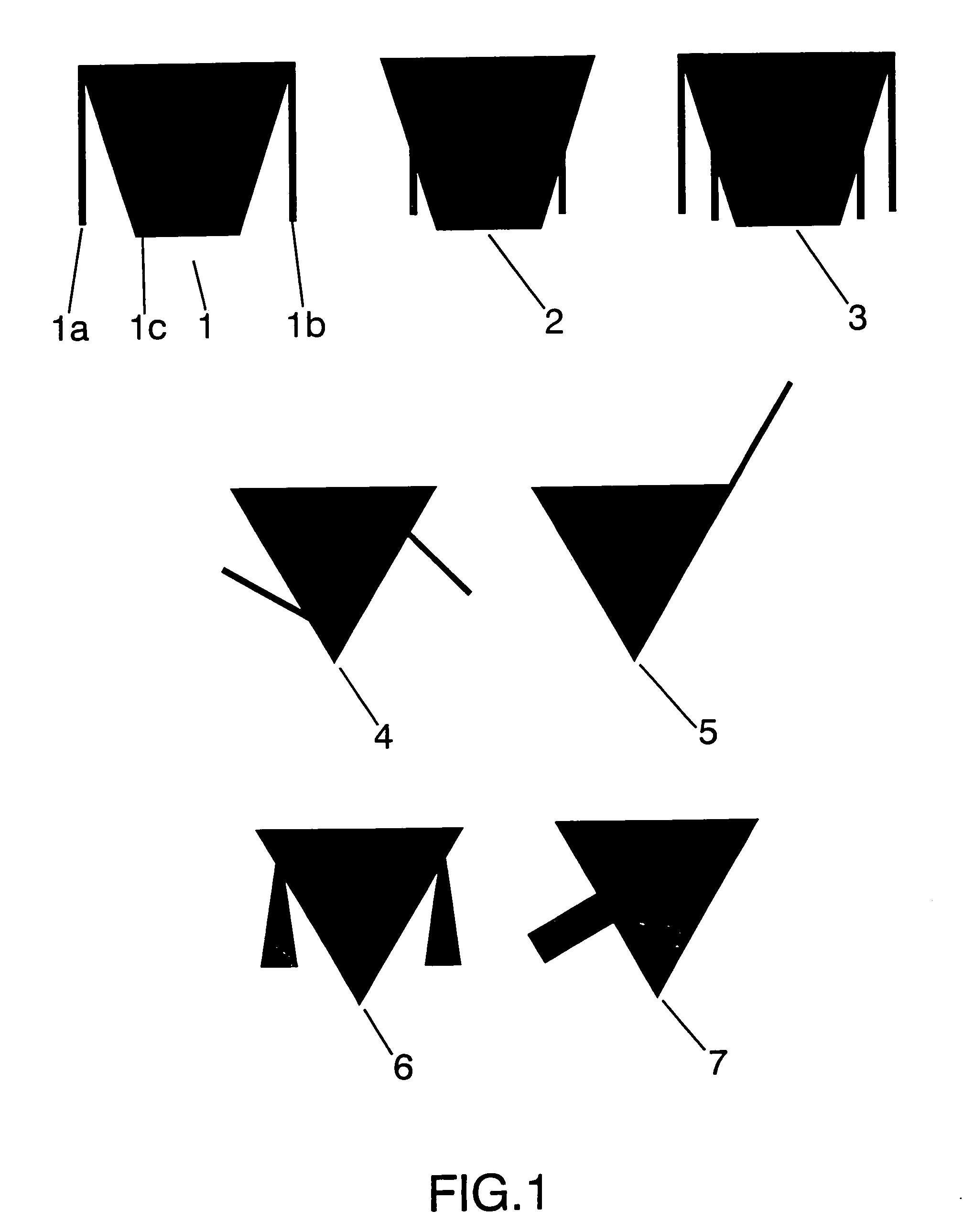
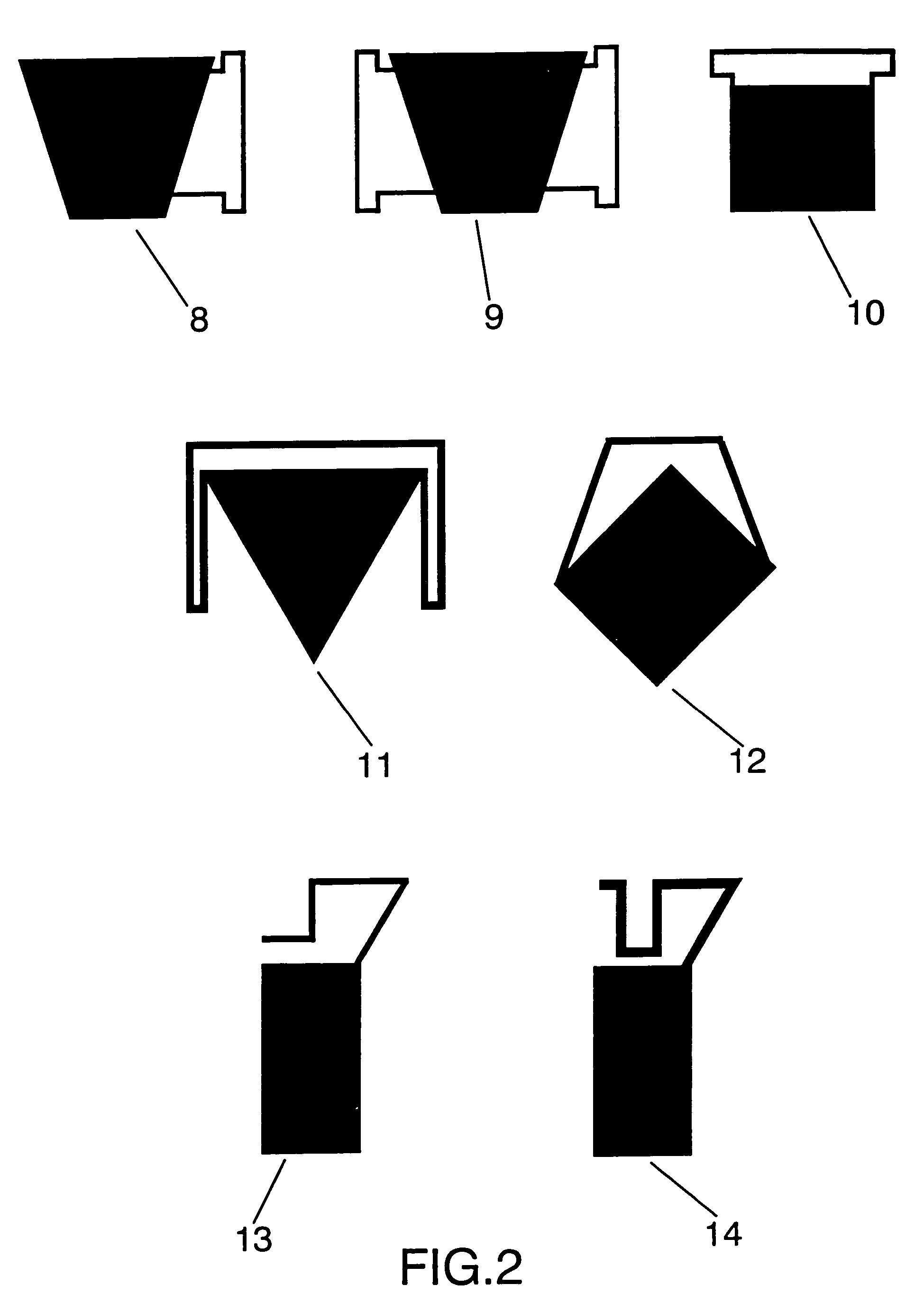
FRACTUS
View PDF231 Cites 85 Cited by
  • Summary
  • Abstract
  • Description
  • Claims
  • Application Information

AI Technical Summary

Problems solved by technology

However, none of these antenna configurations provide a multiband behaviour.

Method used


Image

  • Loaded antenna
  • Loaded antenna
  • Loaded antenna

Examples


Embodiment Construction

[0049]A preferred embodiment of the loaded antenna is a monopole configuration as shown in FIG. 11. The antenna includes a conducting or superconducting counterpoise or ground plane (48). A handheld telephone case, or even a part of the metallic structure of a car or train can act as such a ground conterpoise. The ground and the monopole arm (here the arm is represented with the loaded structure (26), but any of the mentioned loaded antenna structure could be taken instead) are excited as usual in prior art monopole by means of, for instance, a transmission line (47). Said transmission line is formed by two conductors, one of the conductors is connected to the ground counterpoise while the other is connected to a point of the conducting or superconducting loaded structure. In FIG. 11, a coaxial cable (47) has been taken as a particular case of transmission line, but it is clear to any skilled in the art that other transmission lines (such as for instance a microstrip arm) could be u...


PUM


Abstract

A novel loaded antenna is defined in the present invention. The radiating element of the loaded antenna consists of two different parts: a conducting surface and a loading structure. By means of this configuration, the antenna provides a small and multiband performance, and hence it features a similar behaviour through different frequency bands.

Description

[0001]Continuation of prior PCT application No.: EP01 / 11914 filed Oct. 16, 2001.OBJECT OF THE INVENTION[0002]The present invention relates to a novel loaded antenna which operates simultaneously at several bands and featuring a smaller size with respect to prior art antennas.[0003]The radiating element of the novel loaded antenna consists on two different parts: a conducting surface with a polygonal, space-filling or multilevel shape; and a loading structure consisting on a set of strips connected to said first conducting surface.[0004]The invention refers to a new type of loaded antenna which is mainly suitable for mobile communications or in general to any other application where the integration of telecom systems or applications in a single small antenna is important.BACKGROUND OF THE INVENTION[0005]The growth of the telecommunication sector, and in particular, the expansion of personal mobile communication systems are driving the engineering efforts to develop multiservice (mult...

Claims


Application Information

Patent Timeline
Patent Type & Authority Patents(United States)
IPC IPC(8): H01Q9/42H01Q13/08H01Q1/24H01Q1/36H01Q1/38H01Q5/371H01Q9/04H01Q9/28H01Q9/36H01Q9/38H01Q9/40H01Q13/10H01Q15/00
CPCH01Q1/243H01Q1/36H01Q1/38H01Q9/0407H01Q5/371H01Q9/285H01Q9/40H01Q9/42H01Q15/0093H01Q9/0442
Inventor PUENTE BALLARDA, CARLESSOLER CASTANY, JORDI
Owner FRACTUS
Why Eureka
Try Eureka